


GE Analytical Instruments ©2010
55 of 226
DLM 74001-04 Rev. A
Chapter 3: Installation
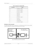
Wiring the Ethernet Cable
Data from the Analyzer may be exported via Ethernet. Attach one end of the cable to the Ethernet port on the
Analyzer’s system board. Attach the other end of the cable either to an Ethernet port on the network or to a
computer. You also must activate the Modbus feature, as described on page 82.
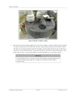
Step 6: Connect the Sample Inlet and Outlet Ports
The flow from the water source should be disabled until the sample inlet system is completely installed and the
Analyzer is ready to begin analysis.
The Analyzer is designed to measure water from a continuous sample flow in On-Line mode; the
iOS
System or
Super
iOS
System can be used to sample from vials when the Analyzer is operated in Grab mode. When taking
measurements from vials (for example, for calibration and verification of the Analyzer), no plumbing change is
required, as 40-mL vials are simply inserted into the
iOS
System, or vials are inserted into the Super
iOS
System.
Follow these steps to configure the sample inlet and outlet ports:
1. Connect the 1/4" Teflon tubing with the in-line filter to the sample inlet on the
iOS
or Super
iOS
System
or the Sample Inlet Block, depending on your Analyzer configuration. Tighten 1/4 turn past finger-tight
with a 9/16" open-end wrench. Do not over-tighten the nut.
2. Connect the 3/4" OD waste line tubing to the waste outlet on the sample inlet system or the Sample
Inlet Block by sliding the tubing over the barb fitting.
3. Place the hose clamp over the waste line and tighten, to secure the connection to the waste outlet.
4. Route the waste tubing to an appropriate waste outlet. Note that the waste is gravity-drained, and thus
the waste tubing cannot be routed above the level of the waste outlet barb.
5. After water flow to the sample inlet system has been established, the flow rate should be adjusted so
that flow out of the waste line is between 50 -300 mL/min. The flow rate is controlled by a needle valve,
Warning
Operation of the Analyzer without the in-line filter on the sample inlet line will
damage the Analyzer and void the warranty. To avoid damaging the Analyzer,
install the filter and replace the filter element as needed.
Warning
To avoid false TOC readings and possible damage to the Analyzer, always make
sure the sample is flowing through the inlet System and the DI water cartridge is
filled before starting analysis.
Содержание Sievers 500 RL
Страница 8: ...GE Analytical Instruments 2010 8 of 226 DLM 74001 04 Rev A ...
Страница 10: ...GE Analytical Instruments 2010 10 of 226 DLM 74001 04 Rev A ...
Страница 36: ...GE Analytical Instruments 2010 36 of 220 DLM 74001 04 Rev A ...
Страница 66: ...GE Analytical Instruments 2010 66 of 226 DLM 74001 04 Rev A Chapter 3 Installation ...
Страница 152: ...GE Analytical Instruments 2010 152 of 226 DLM 74001 04 Rev A Chapter 7 Maintenance ...
Страница 170: ...GE Analytical Instruments 2010 170 of 226 DLM 74001 04 Rev A Chapter 8 Troubleshooting ...
Страница 177: ...Appendix A GE Analytical Instruments 2010 177 of 186 DLM 74001 04 Rev A Figure 51 Left Side Analyzer Dimensions ...
Страница 178: ...Appendix A GE Analytical Instruments 2010 178 of 186 DLM 74001 04 Rev A ...
Страница 185: ...Notes GE Analytical Instruments 2010 185 of 186 DLM 74001 04 Rev A 186 ...
Страница 186: ...Notes GE Analytical Instruments 2010 186 of 186 DLM 74001 04 Rev A 186 ...