GE M
EDICAL
S
YSTEMS
D
IRECTION
2380207, R
EVISION
7
LOGIQ™5 PRO S
ERVICE
M
ANUAL
Chapter 5 Components and Functions (Theory)
5-35
Section 5-8
Power Diagrams
5-8-1
Overview
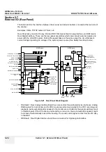
The AC Power assy’s main tasks are to supply the various internal subsystems and to galvanically
isolate the scanner from the on site Mains Power System and to control power on/off. The voltage to
peripherals can be confederated to either 110 VAC or 220 VAC.
5-8-2
AC Power
The mains cord has plugs in one side end. A male plug connects to the mains outlet on site.
The mains voltage is routed to the Main Circuit Breaker, located on the rear of the system.
The Main Circuit Breaker is of the auto fuse type, if for some reason the current grows to high, the switch
will automatically break the power.
From the Main Circuit Breaker, the AC power is routed via an Inrush Current Limiter to a internal outlet
connector for the Mains Transformer.
Figure 5-29 AC Power Assy Block Diagram
AC In
NF
FG
CB
1
2
3
4
J3
Relay
NTC
PTC
FET
FG
V16
FET Driver
isolation
1
2
J6
fuse
Bridge
Transformer
AC 110~220
AC 220
V16
AC 16
1
2
3
4
5
6
J9
fuse
Relay
C
R
Peripheral
AC 110
1
2
3
J2
FET Driver
FET
Relay
C
R
1
2
J11
fuse
1
2
J10
V12
HV B/D
Monitor
AC 110
1
2
J8
1
2
3
J7
VCC
AC 220
7812
7805
V12
VCC
5
6
1
3
J1
2
AC 110
Contol Singal
JPC Assy
4
Содержание LOGIQ 5 PRO
Страница 2: ...GE MEDICAL SYSTEMS DIRECTION 2407381 REVISION 7 LOGIQ 5 PRO SERVICE MANUAL Page 1 2 ...
Страница 3: ......
Страница 7: ...GE MEDICAL SYSTEMS DIRECTION 2380207 REVISION 7 LOGIQ 5 PRO SERVICE MANUAL ii iii ...
Страница 50: ...GE MEDICAL SYSTEMS DIRECTION 2380207 REVISION 7 LOGIQ 5 PRO SERVICE MANUAL 2 12 Section 2 3 Facility Needs ...
Страница 462: ...GE MEDICAL SYSTEMS DIRECTION 2380207 REVISION 7 LOGIQ 5 PRO SERVICE MANUAL A 4 Index INDEX ...

