background image

Technical 
Publication

Direction 2380207
Revision 7

GE Medical Systems
LOGIQ™5 PRO Service Manual

Copyright

©

 2006 by General Electric Co.

Operating Documentation

GE Medical Systems

Содержание LOGIQ 5 PRO

Страница 1: ...Technical Publication Direction 2380207 Revision 7 GE Medical Systems LOGIQ 5 PRO Service Manual Copyright 2006 by General Electric Co Operating Documentation GE Medical Systems ...

Страница 2: ...GE MEDICAL SYSTEMS DIRECTION 2407381 REVISION 7 LOGIQ 5 PRO SERVICE MANUAL Page 1 2 ...

Страница 3: ......

Страница 4: ... Systems Telex 3797371 P O Box 414 Milwaukee Wisconsin 53201 U S A Asia Pacific Latin America North America GE Ultraschall Tel 49 0 212 28 02 207 Deutschland GmbH Co KG Beethovenstrabe 239 Postfach 11 05 60 D 42655 Solingen Germany ...

Страница 5: ...L ANGLAIS C EST AU CLIENT QU IL INCOMBE DE LE FAIRE TRADUIRE NE PAS TENTER D INTERVENTION SUR LES éQUIPEMENTS TANT QUE LE MANUEL SERVICE N A PAS éTé CONSULTé ET COMPRIS LE NON RESPECT DE CET AVERTISSEMENT PEUT ENTRAîNER CHEZ LE TECHNICIEN L OPéRATEUR OU LE PATIENT DES BLESSURES DUES à DES DANGERS éLECTRIQUES MéCANIQUES OU AUTRES DIESES KUNDENDIENST HANDBUCH EXISTIERT NUR IN ENGLISCHER SPRACHE FALL...

Страница 6: ...AIS NOUTRO IDIOMA é DA RESPONSABILIDADE DO CLIENTE FORNECER OS SERVIç OS DE TRADUç ã O Nã O TENTE REPARAR O EQUIPAMENTO SEM TER CONSULTADO E COMPREENDIDO ESTE MANUAL DE ASSISTêNCIA TéCNICA O Nã O CUMPRIMENTO DESTE AVISO PODE POR EM PERIGO A SEGURANç A DO TéCNICO OPERADOR OU PACIENTE DEVIDO A CHOQUES ELéTRICOS MECâ NICOS OU OUTROS IL PRESENTE MANUALE DI MANUTENZIONE è DISPONIBILE SOLTANTO IN INGLES...

Страница 7: ...GE MEDICAL SYSTEMS DIRECTION 2380207 REVISION 7 LOGIQ 5 PRO SERVICE MANUAL ii iii ...

Страница 8: ...ctors Other connections between pieces of electrical equipment calibrations and testing shall be performed by qualified GE Medical Systems personnel In performing all electrical work on these products GE will use its own specially trained field engineers All of GE s electrical work on these products will comply with the requirements of the applicable electrical codes The purchaser of GE equipment ...

Страница 9: ...icated in any form in whole or in part without prior written permission of GE Medical Systems GE Medical Systems may revise this publication from time to time without written notice TRADEMARKS All products and their name brands are trademarks of their respective holders COPYRIGHTS All Material Copyright 2006 by General Electric Inc All Rights Reserved ...

Страница 10: ... 04 software release 4 2005 5 14 LOGIQ 5 BT 05 software release 5 2006 11 10 LOGIQ 5 BT 05 M4 software release 6 2007 3 30 Updated Spare Parts Information on Chapter 9 Content update 7 2008 9 12 Insert the Function check Procedure Pages Revision Pages Revision Pages Revision Title Page 7 1 1 to 1 14 7 Back Cover N A Warnings i to iv 7 2 1 to 2 10 7 Rev Hist LOEP A v to A vi 7 3 1 to 3 28 7 Table o...

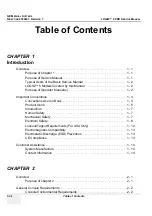
Страница 11: ...perator Manual s 1 2 Important Conventions 1 3 Conventions Used in Book 1 3 Product Icons 1 5 Introduction 1 7 Human Safety 1 7 Mechanical Safety 1 7 Electrical Safety 1 8 Lockout Tagout Requirements For USA Only 1 12 Electromagnetic Compatibility 1 13 Electrostatic Discharge ESD Prevention 1 13 CE Compliance 1 13 Customer Assistance 1 14 System Manufacture 1 14 Contact Information 1 14 CHAPTER 2 ...

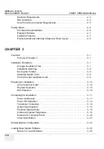
Страница 12: ...ge Installation Time 3 1 Installation Warnings 3 2 Moving into Position 3 9 Adjusting System Clock 3 9 Product Locator Installation Card 3 9 Preparing for Installation 3 10 Verify Customer Order 3 10 Physical Inspection 3 10 EMI Protection 3 10 Completing the Installation 3 11 Power On Boot Up 3 11 Power Off Shutdown 3 14 Transducer Connection 3 14 System Specifications 3 15 Electrical Specificati...

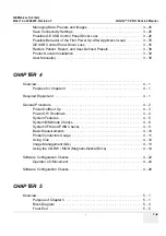
Страница 13: ...or Installation 3 39 User Manual s 3 39 CHAPTER 4 Overview 4 1 Purpose for Chapter 4 4 1 Required Equipment 4 1 General Procedure 4 2 Power On Boot Up 4 3 Power Off Shutdown 4 4 System Features 4 5 System B M Mode Checks 4 8 System CFM and PWD Checks 4 9 Basic Measurements 4 10 Probe Connectors Usage 4 11 Using Cine 4 12 Image Management QG 4 13 Using the CD RW MOD Magneto Optical Drive 4 14 Softw...

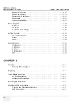
Страница 14: ...er Low Voltage 5 25 Air Flow Control 5 28 Air Flow Distribution 5 28 Filters 5 28 Fans 5 29 Service Platform 5 30 Introduction 5 30 Calibration 5 38 Utilities 5 39 Replacement 5 39 PM 5 40 CHAPTER 6 Overview 6 1 Purpose of this chapter 6 6 1 Regulatory 6 1 Power Supply Adjustment 6 2 LV Unit Disassembly 6 2 Adjustments Procedures 6 4 Reloading the Probe Data 6 5 Monitor and LCD Adjustments 6 8 Con...

Страница 15: ...e of Chapter 8 8 1 DISAS SEMBLY RE ASSEMBLY 8 1 Monitor 8 2 CRT Assy FRU No 100 8 2 Monitor Cable Assy FRU No 101 8 4 Monitor Cover Set FRU No 102 8 6 Monitor S W Assy FRU No 103 8 7 Speaker Assy FRU No 104 8 9 Task Lamp Assy FRU No 105 8 11 Keyboard Block 8 13 KeyBoard Assy FRU No 200 8 13 KeyBoard Front Grip FRU No 201 8 15 Probe Holder FRU No 202 8 16 ECG Cable Hook FRU No 203 8 17 OP Panel Enc...

Страница 16: ...R FRU No 313 8 49 Side Cap FRU No 314 8 50 Side Fringe FRU No 315 8 51 Body Block 8 52 Rear Handle FRU No 400 8 52 Rear Panel Assy FRU No 401 8 54 Gas Spring Assy FRU No 402 8 56 Front Caster FRU No 403 8 58 Rear Caster FRU No 404 8 59 Bumper Set FRU No 405 8 60 Air Filter Set FRU No 406 8 61 PCB Boards 8 62 RLY Assy FRU No 500 8 62 LMT Assy FRU No 501 8 64 BackPlane FRU No 502 8 66 PCB Boards FRU...

Страница 17: ...99 Loading Applications Software 8 105 System Setup 8 108 Installation an Optional USB Line Printer 8 109 CHAPTER 9 Renewal Parts Overview 9 1 Purpose of Chapter 9 9 1 List of Abbreviations 9 1 Renewal Parts Lists 9 2 Equipment Models Covered in this Chapter 9 2 CHAPTER 10 Periodic Maintenance Overview 10 1 Purpose of Chapter 10 10 1 Why do Periodic Maintenance 10 2 Keeping Records 10 2 Quality As...

Страница 18: ...g 10 7 Physical Inspection 10 8 Probe Maintenance 10 9 Using a Phantom 10 10 Electrical Safety Tests 10 10 Safety Test Overview 10 10 Grounding Continuity 10 12 Isolated Patient Lead Source Leakage Lead to Ground 10 16 Isolated Patient Lead Source Leakage Lead to Lead 10 17 Isolated Patient Lead Sink Leakage Isolation Test 10 18 ...

Страница 19: ...hecks Contains functional checks that are recommended as part of the installation or as required during servicing and periodic maintenance 5 Chapter 5 Components and Functions Theory Contains block diagrams and functional explanations of the electronics 6 Chapter 6 Service Adjustments Contains instructions on how to make available adjustments to the LOGIQ 5 PRO 7 Chapter 7 Diagnostics Troubleshoot...

Страница 20: ...r 2 Pre Installation 1 1 4 LOGIQ 5 PRO Models Covered by this Manual 1 1 5 Purpose of Operator Manual s The Operator Manual s should be fully read and understood before operating the LOGIQ 5 PRO and also kept near the unit for quick reference Table 1 2 LOGIQ 5 PRO Model Designations Part Number Description 2381304 LOGIQ 5 PRO Console for Japan 2381301 LOGIQ 5 PRO Console for USA 2381302 LOGIQ 5 PR...

Страница 21: ...ial hazards are labeled in one of following ways NOTE Notes provide important information about an item or a procedure Information contained in a NOTE can often save you time or effort DANGER DANGER IS USED TO INDICATE THE PRESENCE OF A HAZARD THAT WILL CAUSE SEVERE PERSONAL INJURY OR DEATH IF THE INSTRUCTIONS ARE IGNORED WARNING WARNING WARNING IS USED TO INDICATE THE PRESENCE OF A HAZARD THAT CA...

Страница 22: ...ddition to text several different graphical icons symbols may be used to make you aware of specific types of hazards that could cause harm Other hazard icons make you aware of specific procedures that should be followed Table 1 3 Standard Hazard Icons ELECTRICAL MECHANICAL RADIATION LASER HEAT PINCH Table 1 4 Standard Icons Indicating a Special Procedure Be Used AVOID STATIC ELECTRICITY TAG AND LO...

Страница 23: ... degree of protection provided by the enclosure per IEC 529 IPX8 indicates drip proof Footswitch Equipment Type BF man in the box symbol IEC 878 02 03 indicates B Type equipment having even more electrical isolation than standard Type B equipment because it is intended for intimate patient contact Probe connectors PCG connector or Rear of Console Equipment Type CF heart in the box symbol IEC 878 0...

Страница 24: ... Supply Adjacent to On Off Standby Switch Mains ON Indicates the power on position of the mains power switch ON Indicates the power on position of the power switch CAUTION This Power Switch DOES NOT ISOLATE Mains Supply Front Panel Switch Protective Earth Indicates the protective earth grounding terminal Internal Equipotentiality Indicates the terminal to be used for connecting equipotential condu...

Страница 25: ...mace týkající se likvidace vašeho přístroje Dette symbol angiver at elektrisk og elektronisk affald ikke må bortskaffes som usorteret brændbart affald men skal indsamles særskilt Kontakt venligst en autoriseret repræsentant for producenten for at få oplysninger om hvordan dit udstyr skal bortskaffes Dit symbool geeft aan dat het afval van elektrische en elektronische apparatuur niet ongescheiden m...

Страница 26: ... und elektronische Geräte die nicht mit dem gewöhnlichen unsortierten Hausmüll entsorgt werden dü rfen sondern separat behandelt werden müssen Bitte nehmen Sie Kontakt mit einem autorisierten Beauftragten des Herstellers auf um Informationen hinsichtlich der Entsorgung Ihres Gerätes zu erhalten Αυτό το σύµβολο υποδηλώνει ότι τα απόβλητα ηλεκτρικού και ηλεκτρονικού εξ οπλισµού δεν πρέπει να απορρίπ...

Страница 27: ...informāciju par aprīkojuma ekspluatācijas pā rtraukšanu Šis simbolis nurodo kad elektros ir elektroninės įrangos atliekos turi būti surenkamos atskirai ir negali būti šalinamos kaip nerūšiuotos savivaldybė s tvarkomos atliekos Informacijos apie įrangos veikimo sustabdymą kreipkitės į įgaliotąjį gamintojo atstovą Dette symbolet angir at elektrisk og elektronisk utstyr ikke skal kastes som restavfal...

Страница 28: ...no sa običnim gradskim smećem već se mora pokupiti posebno Molimo vas da kontaktirate ovlašćenog predstavnika proizvođača svoje opreme kako bi ste se informisali o njenom pravilnom rashodu Tento symbol označuje že odpad elektrického a elektronického materiá lu sa nesmie vyhadzovať do netriedeného komunálneho odpadu ale mus í sa likvidovať oddelene Viac informácií o likvidácii vášho zariadenia vám ...

Страница 29: ...ic element Pb Lead Cd Cadmium Hg Mercury that is contained in the battery that may require special recycling or disposal method Please contact a GEHC representative to facilitate servicing removal and disposal options Table 1 6 WEEE Label Continued LABEL SYMBOL LANGUAGE PURPOSE MEANING Bu sembol elektrikli ve elektronik ekipmanların sınıflandırılmamış çöp olarak atılmaması ve ayrı olarak toplanmas...

Страница 30: ...ALONG ANY INCLINE USE EXTREME CAUTION SINCE IT MAY BECOME UNSTABLE AND TIP OVER WARNING WARNING ULTRASOUND PROBES ARE HIGHLY SENSITIVE MEDICAL INSTRUMENTS THAT CAN EASILY BE DAMAGED BY IMPROPER HANDLING USE CARE WHEN HANDLING AND PROTECT FROM DAMAGE WHEN NOT IN USE DO NOT USE A DAMAGED OR DEFECTIVE PROBE FAILURE TO FOLLOW THESE PRECAUTIONS CAN RESULT IN SERIOUS INJURY AND EQUIPMENT DAMAGE WARNING ...

Страница 31: ...e connected to an electrical ground The system is equipped with a three conductor AC power cable This must be plugged into an approved electrical outlet with safety ground If an extension cord is used with the system make sure that the total current rating of the system does not exceed the extension cord rating The power outlet used for this equipment should not be shared with other types of equip...

Страница 32: ... the symbols shown in the illustration below refer to previous pages in this chapter 1 Caution for Possible injury Never put any device onto the Monitor 2 Caution for Hazardous movement Inside of the OP rear Cover 3 Defibrillator Label Do not use with Defibrillator On optional ECG Module Figure 1 1 OUTSIDE MARKINGS OF LOGIQ 5 PRO Monitor 1 2 3 ...

Страница 33: ...Devices 5 CE Mark Label 6 CISPR Label 7 Voltage Range Indication Label 8 Power Indication Label 9 Grounding reliability Label Figure 1 2 OUTSIDE MARKINGS OF LOGIQ 5 PRO Rear 220 240V 500VA Max Including front printer panel 100 120V 500VA Max Including front printer panel Japan USA Asia Console 100 120V Europe USA Console 220V 1 3 4 5 6 2 7 AC Line Input Circuit Breaker 100 120V 50 60Hz On Off 1250...

Страница 34: ...in America 220V Console 4 Identification and Rating Plate Japan 100V Console 5 Identification and Rating Plate Korea 220V Console 6 Caution EIAJ Label 7 Identification and Rating Plate China 220V Console Figure 1 3 OUTSIDE MARKINGS OF LOGIQ 5 PRO Korea 220V Console 1 2 3 4 5 6 GE ULTRASOUND KOREA LTD 1250VA 1250VA 1250VA 120V GE ULTRASOUND Korea GE ULTRASOUND KOREA China 220V Console 7 LOGIQ 5 PRO...

Страница 35: ...ring you are in total control of the electrical Mains plug DANGER DANGEROUS VOLTAGES CAPABLE OF CAUSING DEATH ARE PRESENT IN THIS EQUIPMENT USE EXTREME CAUTION WHEN HANDLING TESTING AND ADJUSTING WARNING WARNING EXPLOSION WARNING DO NOT OPERATE THE EQUIPMENT IN AN EXPLOSIVE ATMOSPHERE OPERATION OF ANY ELECTRICAL EQUIPMENT IN SUCH AN ENVIRONMENT CONSTITUTES A DEFINITE SAFETY HAZARD WARNING WARNING ...

Страница 36: ...e effects from electrical fields magnetic fields electrostatic discharge and disturbances in the electrical power supply 1 4 2 CE Compliance The LOGIQ 5 PRO unit conforms to all applicable conducted and radiated emission limits and to immunity from electrostatic discharge radiated and conducted RF fields magnetic fields and power line transient requirements For applicable standards refer to the Sa...

Страница 37: ... Number USA Canada GE Medical Systems Ultrasound Service Engineering 4855 W Electric Avenue Milwaukee WI 53219 Customer Answer Center 1 800 437 1171 1 800 682 5327 1 262 524 5698 Fax 1 414 647 4125 Latin America GE Medical Systems Ultrasound Service Engineering 4855 W Electric Avenue Milwaukee WI 53219 Customer Answer Center 1 262 524 5300 1 262 524 5698 Fax 1 414 647 4125 Europe GE Ultraschall De...

Страница 38: ...LOGIQ 5 PRO SERVICE MANUAL 1 20 Section 1 5 Customer Assistance 1 5 2 System Manufacturer Table 1 8 System Manufacturer Manufacturer FAX Number GE Ultrasound Korea 462 120 65 1 Sangdaewon dong Joong won Gu Seongnam Si Gyeonggi do Korea 82 31 740 6436 ...

Страница 39: ... installation of a LOGIQ 5 Included are descriptions of the facility and electrical needs to be met by the purchaser of the unit A checklist is also provided at the end of this section to help determine whether the proper planning and preparation is accomplished before the actual equipment installation is scheduled Table 2 1 Contents in Chapter 2 Section Description Page Number 2 1 Overview 2 1 2 ...

Страница 40: ...ted to minimize possible interface 2 2 2 Electrical Requirements NOTE GE Medical Systems requires a dedicated power and ground for the proper operation of its Ultrasound equipment This dedicated power shall originate at the last distribution panel before the system Table 2 2 Environmental Requirements for LOGIQ 5 Scanners Operational Storage Transport Temperature 10 35 oC 50 104 oF 10 60 oC 14 140...

Страница 41: ...ing properties of the power supplies 2 2 2 3 Site Circuit Breaker It is recommended that the branch circuit breaker for the machine be ready accessible 2 2 2 4 Site Power Outlets A desiccated AC power outlet must be within reach of the unit without extension cords Other outlets adequate for the external peripherals medical and test equipment needed to support this unit must also be present within ...

Страница 42: ... as stated on the EMC label However there is no guarantee that interface will not occur in a particular installation Possible EMI sources should be identified before the unit is installed Electrical and electronic equipment may produce EMI unintentionally as the result of defect These sources include medical lasers scanners cauterizing guns computers monitors fans gel warmers microwave ovens light...

Страница 43: ...ere RF gaskets touch metal Never place a label where RF gaskets meet the unit Otherwise the gap created will permit RF leakage Or if a label has been found in such a position move the label Use GE specified harnesses and peripherals The interconnect cables are grounded and require ferrite beads and other shielding Also cable length material and routing are all important do not change from what is ...

Страница 44: ...es should be made known to the individuals or group performing the installation at the earliest possible date preferable prior to purchase The ultrasound suite must be clean proof to delivery of the machine Carpet is not recommended because it collects dust and creates static Potential sources of EMI electromagnetic interference should also be investigated before delivery Dirt static and EMI can n...

Страница 45: ...ide the unit One is for the monitor and three for on board peripherals Power outlets for other medical equipment and gel warmer Power outlets for test equipment and modem within 1 m 3 2 ft of unit Clean and protected space to store transducers in their cases or on a rack Material to safely clean probes done with a plastic container never metal ...

Страница 46: ...e Circuit breaker for dedicated power outlet is easily accessible Sink with hot and cold water Receptacle for bio hazardous waste like used probe sheaths Emergency oxygen supply Storage for linens and equipment Nearby waiting room lavatory and dressing room Dual level lighting bright and dim Lockable cabinet ordered by GE for its software and proprietary manuals ...

Страница 47: ...EDICATED POWER RECEPTACLE EXTERNAL PERIPHERALS SINK COUNTER TOP FILM VIEWER FILM SUPPLIES SINK LINEN SUPPLY PROBES SUPPLIES 24 IN 61 CM EXAMINARION TABLE 76 IN 193 CM DOOR 30 IN 76 CM An 8 by 10 foot Minimal Floor Plan DEDICATED POWER OUTLETS DEDICATED ANALOG TELEPHONE LINE FOR CONNECTION TO INSITE A 14 by 17 foot Recommended Floor Plan GE CABINET FOT SOFTWARE AND MANUALS Scale Each square equals ...

Страница 48: ...to be done while scanning continues With DICOM images can be archived stored and retrieved faster easier and at a lower cost 2 3 5 2 DICOM Option Pre installation Requirements To configure the LOGIQ 5 to work with other network connections the site s network administrator must provide some necessary information Information must include A host name local port number AE Title IP address and Net Mask...

Страница 49: ...t d Figure 2 2 Worksheet for DICOM Network Information LOGIQ 5 Host Name AE Title Local Port IP Address Net Mask ROUTING INFORMATION ROUTER2 ROUTER3 ROUTER1 Destination IP Addresses GATEWAY IP Addresses Default DICOM APPLICATION INFORMATION NAME Store 2 Store 3 Store 1 MAKE REVISION IP ADDRESSES PORT AE TITLE Store 5 Store 6 Store 4 Storage Commit MPPS Worklist ...

Страница 50: ...GE MEDICAL SYSTEMS DIRECTION 2380207 REVISION 7 LOGIQ 5 PRO SERVICE MANUAL 2 12 Section 2 3 Facility Needs ...

Страница 51: ...d external peripherals for electrical safety are included in this procedure Also included in this section are guidelines for transporting the unit to a new site Table 3 1 Contents in Chapter 3 Section Description Page Number 3 1 Overview 3 1 3 2 Installation Reminders 3 2 3 3 Receiving and Unpacking the Equipment 3 4 3 4 Preparing for Installation 3 9 3 5 Completing the Installation 3 11 3 6 Syste...

Страница 52: ...ice personnel should carry out servicing and troubleshooting NOTE For information regarding packing labels refer to LABELS ON PACKAGE 3 After being transported the unit may be very cold or hot If this is the case allow the unit to acclimate before you turn it on It requires one hour for each 2 5 C increment if its temperature is below 10 C or above 40 C Table 3 2 Average Installation Time Descript...

Страница 53: ...ts safety grounding CAUTION Do NOT wear the ESD wrist strap when you work on live circuits and more than 30 V peak is present CAUTION Do not use a 20 Amp to 15 Amp adapter on the 120 Vac unit s power cord This unit requires a dedicated 20 A circuit and can have a 15A plug if the on board peripherals do not cause the unit to draw more than 14 0 amps CAUTION Do not operate this unit unless all board...

Страница 54: ...are not damaged and are not in short supply If shipping damage or shortage occurs contact the address shown in Chapter 1 1 Cut the three PLASTIC BANDs Figure 3 7 Cutting the Plastic Bands CAUTION Do not lift the unit by the Keyboard Equipment damage may result CAUTION The crate with the LOGIQ 5 PRO weighs approximately 180 kg 397 lb Be prepared for a sudden shift of weight as the unit is removed f...

Страница 55: ...MS DIRECTION 2380207 REVISION 7 LOGIQ 5 PRO SERVICE MANUAL Chapter 3 Installation 3 5 Section 3 3 Receiving and Unpacking the Equipment cont d 2 Lift the TOP COVER up and off Figure 3 8 Removing the top Cover Top Cover ...

Страница 56: ...07 REVISION 7 LOGIQ 5 PRO SERVICE MANUAL 3 6 Section 3 3 Receiving and Unpacking the Equipment Section 3 3 Receiving and Unpacking the Equipment cont d 3 Remove the MONITOR CAP up and off Figure 3 9 Removing the monitor cap Monitor Cap ...

Страница 57: ...ation 3 7 Section 3 3 Receiving and Unpacking the Equipment cont d 4 Remove the three PLASTIC JOINTs from the OUTER SLEEVE 5 Remove the OUTER SLEEVE 6 Remove the INNER SLEEVE Figure 3 10 Removing Plastic Joints and Sleeves Plastic Joint Outer Sleeve Inner Sleeve Palette Assy Monitor Supporter ...

Страница 58: ... d 7 Remove the PLASTIC BAG 8 Lift the Monitor up by pressing the UP Down Release Button 9 Remove the MONITOR SUPPORTER 10 Pull the Bottom Plate from the bottom so that it can be used as a ramp 11 Unlock the front caster and carefully put the console off the PALETTE Figure 3 11 Moving the LOGIQ 5 PRO from the crate PLASTIC BAG Palette Base Assy Console Monitor Supporter Bottom Plate ...

Страница 59: ... system clock refer to section 3 6 1 1 on page 16 Fill out proper customer Information the Product Locator Installation Card Mail this Installation Card Product Locator to the address corresponding to your pole 3 3 3 Product Locator Installation Card NOTE The Product Locator Installation Card shown may not be same as the provided Product Locator card Section 3 4 Preparing for Installation 3 4 1 Ve...

Страница 60: ...UTSIDE MARKINGS OF LOGIQ 5 PRO on page 1 16 3 4 2 2 Video Formats Check that the video format is set to the locally used video standard NTSC or PAL 3 4 3 EMI Protection This Unit has been designed to minimize the effects of Electro Magnetic Interference EMI Many of the covers shields and screws are provided primarily to protect the system from image artifacts caused by this interference For this r...

Страница 61: ... Circuit Breaker at the rear of the System When power is applied to the Scanner and the Rear Circuit breaker is turned ON Power is distributed to the ATX smps in the Back End Processor and Power control circuit in the AC power assy When the Power ON OFF key is pressed once the power control circuit turn on the card cage and fans and Back End Processor Monitor Backend Processor starts and its softw...

Страница 62: ...e 1 The Start Up Screen will be shown on the Monitor display when the system is turned ON 2 After initialization is complete default mode buttons on the keyboard are lit and the B Mode screen or Patient screen no probes are connected is displayed on the monitor Figure 3 14 Power On Off Switch Location Figure 3 15 Start Up Screen Display Power B W Printer Composite B W Serial ...

Страница 63: ...e 1 If the service dongle is inserted in the USB port in the rear panel during system boot up Maintenance access window appears 2 Then key in the service pass word and click OK button 3 When the start application widow appear click the Maintenence button NOTE Start is selected automatically when it time out Figure 3 16 maintenance Window ...

Страница 64: ...it dialog box as Figure 3 17 on page 3 14 3 Switch OFF the Main Circuit Breaker at the rear of the system Refer to Figure 3 13 on page 3 11 4 Disconnect the Main Power Cable is necessary For example Relocating the scanner Figure 3 17 System Exit Window NOTICE Disconnecting the Mains Power Cable before switching OFF the Circuit Breaker will activate the uninterruptible power system UPS in the backe...

Страница 65: ...s A Ensure that the transducer twist lock lever to the horizontal position B Insert the transducer connector on the receptacle guide pin until it touches the receptacle mating surface C Twist the transducer twist lock lever to vertical position to lock it in place Twist the lever to the horizontal position to disconnect the transducer NOTE It is not necessary to turn OFF power to connect or discon...

Страница 66: ...lick on Logoff 3 The message window appears Click on OK 4 The OPERATOR LOGIN window appears Change the User level to Admin then enter Password Then click on Log on Table 3 1 System Configuration Configuration Category Description Settings Enables the user or service personnel to set the date time unit language basic information about the organization such as the institution name and department Fig...

Страница 67: ... and Time Language and Units Click on Utilities to terminate the utility function 3 6 1 2 Physical Dimensions The physical dimensions of the LOGIQ 5 PRO unit are summarized in Table 3 2 on page 3 17 The Size of LOGIQ 5 PRO with monitor and peripherals Figure 3 20 Setting Display Table 3 2 Physical Dimensions of LOGIQ 5 PRO Height Width Depth Unit 135 145 52 0 99 0 cm 53 1 57 08 20 47 38 9 inches ...

Страница 68: ...sical Dimensions cont d Figure 3 21 Overall Dimensions Table 3 3 Weight of LOGIQ 5 PRO With Monitor and Without Other Peripherals Model Weight kg Weight lbs LOGIQ 5 PRO Approximately 180 Approximately 397 Table 3 4 Electrical Specifications for LOGIQ 5 PRO System Voltage Current Frequency 1 110 120 VAC 10 12A 50 60Hz 2 220 240 VAC 5 5 5A 50 60Hz 1350 1450 800 900 520 990 WEIGHT 180Kg 397lbs includ...

Страница 69: ...wer connector and control connections for VCR printer and service tools Table 3 5 List of Recording Devices Device Manufacturer Model Video Signal B W Video Printer SONY UP 895MDW UPD 895 NTSC PAL B W Video Printer Mitsubishi P 91 AP9500 P91W P91E P91D NTSC NTSC PAL NTSC PAL Video Cassette Recorder SONY SVO 9500MD SVO 9500 MDP NTSC PAL Video Cassette Recorder Panasonic AG MD835 AG MD835P AG MD835E...

Страница 70: ...dicates the pin assignment for each connector NOTE Each outer case ground line of peripheral accessory connectors are protectively grounded Signal ground lines are not isolated except the Service port 3 All of signal lines include signal GND of the Service port are isolated Figure 3 22 Rear Connector Panel 220 240V 500VA Max Including front printer panel 1 2 Serial 1 2 ...

Страница 71: ...4 DTR 9 N A 5 GND Table 3 6 Pin Assignments of RS232C for Remote 1 and Remote 2 Pin No Signal Pin No Signal 1 NC 6 NC 2 RXD 7 NC 3 TXD 8 NC 4 NC 9 RI 5 GND Table 3 7 Pin Assignments of RS232C for Service Pin No Signal Pin No Signal 1 RED 9 N A 2 GREEN 10 SGND 3 BLUE 11 N A 4 N A 12 N A 5 GND 13 HSYNC 6 RGND 14 VSYNC 7 GGND 15 N A 8 BGND Table 3 8 Pin Assignments of DB15 connector for External VGA ...

Страница 72: ...No Signal Pin No Signal 1 TX 5 NC 2 TX 6 RX 3 RX 7 NC 4 NC 8 NC Table 3 10 Pin Assignments of InSite RJ45 Male Connector Pin No Signal Pin No Signal 1 TX 5 NC 2 TX 6 RX 3 RX 7 NC 4 NC 8 NC Table 3 11 Pin Assignments of Ethernet Pin No Output Signal 1 PRINT 1 2 Signal GND Table 3 12 Pin Assignment of Mini Jack for Controlling B W Printer Pin No Output Signal 1 SHUTTER 2 2 Signal GND Table 3 13 Pin ...

Страница 73: ...68 Pixel Clock MHz 78 75 29 50 24 55 40 00 49 50 65 00 H Blank Width µs 3 66 5 97 5 70 6 40 5 17 4 92 H Sync Width µs 1 22 2 34 2 36 3 20 1 62 2 09 H Front Porch µs 0 20 0 75 0 73 1 00 0 32 0 37 Active Horizontal Period µs 13 00 26 03 26 07 20 00 16 16 15 75 Vertical Rate Hz 75 03 50 00 59 94 60 32 75 00 60 00 Vertical Period ms 13 33 20 00 16 68 16 58 13 33 16 67 V Sync Width lines ms 32 0 53 49 ...

Страница 74: ...ent probes Section 3 8 Software Option Configuration Refer to the LOGIQ 5 PRO Basic User Manual Chapter 16 Customizing Your System for information on configuring items like Hospital Department Language Units of measure Date Time and Date Format For information on configuring Software Options Refer to the LOGIQ 5 PRO Basic User Manual Chapter 16 Customizing Your System For information on configurin...

Страница 75: ... Information Services Destination Devices TCP IP Settings Device Type Manufacturer Name IP Address Port AE Title 1 2 3 4 5 6 7 8 9 10 11 12 Name AE Title Dept LOGIQ SN Type Floor Room REV Comments CONTACT INFORMATION Name Title Phone E Mail Address Site IP Settings IP Address Subnet Mask Default Gateway Remote Archive Setup Remote Archive IP Remote Archive Name ...

Страница 76: ...is available during the operation and service of the complete system 3 10 1 Product Locator Installation NOTE The Product Locator Installation Card shown may not be same as the provided Product Locator card 3 10 2 User Manual s Check that the correct User Manual s for the system and software revision is included with the installation Specific language versions of the User Manual may also be availa...

Страница 77: ...quired Equipment An empty blank MO Disk At least one transducer See Probe Connectors Usage QG on page 28 for an overview normally you should check all the transducers used on the system Table 4 15 Contents in Chapter 4 Section Description Page Number 4 1 Overview 4 1 4 2 Required Equipment 4 1 4 3 General Procedure 4 2 4 4 Software Configuration Checks 4 20 4 5 Peripheral Checks 4 21 4 6 Periphera...

Страница 78: ...m 2 Ensure the Cable Clip slips securely over the shoulders on the molded plug 3 Connect the Main Power cable to an appropriate mains power outlet 4 Switch ON the Main Circuit Breaker at the rear of the System CAUTION SYSTEM REQUIRES ALL COVERS Operate this unit only when all board covers and frame panels are securely in place The covers are required for safe operation good system performance and ...

Страница 79: ...ker is turned ON Power is distributed to the ATX smps in the Back End Processor and Power control circuit in the AC power assy When the Power ON OFF key is pressed once the power control circuit turn on the card cage and fans and Back End Processor Monitor Backend Processor starts and its software code is distributed to initiate the scanner Figure 4 24 Circuit Breaker Main Power Cable Main Circuit...

Страница 80: ...turning off a system wait at least ten seconds before turning it on again The system may not be able to boot if power is recycled too quickly 4 3 2 1 Scanner shutdown 1 Press the On Off key at the front of the system once to display the SYSTEM EXIT menu 2 Select Shutdown from the SYSTEM EXIT menu Figure 4 25 Power On Off Standby Switch Location Figure 4 26 System Exit Menu for System Shutdown Powe...

Страница 81: ...ple Servicing or relocating the scanner 4 3 3 System Features 4 3 3 1 Control Panel 1 Video 2 Audio On Off and Volume 3 TGC 4 Reverse 5 Additional Feature Keys 6 Keyboard 7 Mode Gain Keys 8 Imaging Measurement Keys 9 Depth NOTICE Disconnecting the Mains Power Cable before switching OFF the Circuit Breaker will activate the uninterruptible power system UPS in the Back End Processor forcing an order...

Страница 82: ... Activates Image Management and Measurement Selection Menu with end of exam options 4 Utility Activates the configuration system 5 Applications Select the application to use and Probe select 6 Mode Paramenters To toggle between the Primary menus of different modes 7 Top menu Controls Activates the changes of functions in the Top menu 8 Sub menu controls Activates Sub Menu for Modes and toggles cha...

Страница 83: ...ientation Marker Coincides with a probe orientation marking on the probe 5 Image Preview 6 Gray Color Bar 7 Cine Gauge 8 Measurement selection Menu 9 Image 10 Measurement 11 Result window 12 Imaging Paramenters by mode 13 Power Output Readout system status 14 Focal Zone 15 Depth Scale 16 Body Pattern 17 TGC 18 Image Management Menu Menu Delete and Image Manager 19 Image Palette 20 System Messages ...

Страница 84: ... amplitude before it will be processed Edge Enhance Edge Enhance brings out subtle tissue differences and boundaries by enhancing the gray scale differences corresponding to the edges of structures Adjustments to M Mode s edge enhancement affects the M Mode only Frame Average Temporal filter that averages frames together This has the effect of presenting a smoother softer image Colorize Enables gr...

Страница 85: ...cific color map to be selected After a selection has been made the color bar displays the resultant map Invert Allows blood flow to be viewed from a different perspective i e red away negative velocities and blue toward positive velocities The real time or frozen image can be inverted Packet Size Controls the number of samples gathered for a single color flow vector Quick Angle Correct Quickly adj...

Страница 86: ...TE After you complete the measurement to erase all data that has been measured to this point but not data entered onto worksheets press CLEAR 4 3 6 2 Circumference Area Ellipse Measurement 1 Press MEASURE once an active caliper displays 2 To position the active caliper move the TRACKBALL 3 To fix the start point press SET The system fixes the first caliper and displays a second active caliper 4 To...

Страница 87: ...asurements and calculations There are generic worksheets as well as Application specific worksheets The worksheets are selected from the Measurement icon on the monitor screen after pressing measurement key 4 3 6 4 Report Pages Measurements Calculations that are included on the worksheet can also be displayed on Report Pages Report Pages can be customized to meet the appropriate needs of the user ...

Страница 88: ...robe indicators on the monitor screen The probe activates in the currently selected operating mode The probe s default settings for the mode and selected exam are used automatically 4 3 7 3 Deactivating the probe When deactivating the probe the probe is automatically placed in standby mode 1 Press the Freeze key 2 Gently wipe the excess gel from the face of the probe Refer to the Basic User Manual...

Страница 89: ...d through the CINE Loop 4 3 8 4 Adjusting the CINE Loop Playback Speed Turn the LOOP SPEED dial right left to increase decrease the CINE Loop playback speed 4 3 8 5 Disconnecting B Mode CINE from Timeline CINE To review the B Mode CINE Loop only press CINE MODE SELECTION and select B ONLY To review the Timeline CINE Loop only press CINE MODE SELECTION and select TL ONLY To return to linked B Mode ...

Страница 90: ...rder of use are a Press EJECT button on the CD RW while system is ON b Press and hold EJECT button while the system is booting c Mechanical ejection Insert the end of a paper clip into the hole next to the EJECT button while system power is OFF NOTICE Never move the unit with a disk in the CD RW because the drive actuator will not be locked and the CD RW could break NOTICE Avoid mechanical ejectio...

Страница 91: ...nsert the disk into the MOD with the label facing up 3 There are different methods to eject a disk from the MOD In some cases disk ejection is automatic Manual ejection methods are listed below in preferred order from best 1 to worst 4 a When in Archive Menu use the softkey choice or click Image Presets up then click the left softkey switch up for ARCHIVE then toggle the switch under EJECT MOD b P...

Страница 92: ... is best to use all capital letters with no spaces or punctuation marks 5 The Ultrasound system displays a pop up menu as shown in Figure 4 32 When the formatting has been completed press OK to continue 6 If desired verify that the format was successful by returning to Utility Connectivity Tools in case of BT05 SW Removable Media and selecting VERIFY as shown in Figure 4 31 NOTICE Avoid mechanical...

Страница 93: ... drive 2 On the Touch Panel press UTILITY 3 On the Utility Touch Panel press SYSTEM 4 On the monitor display select BACKUP RESTORE NOTE If you are not logged in as GE Service or with administrator privileges the Operator Login window is displayed Log on with administrator privileges 5 In the Backup list select Patient Archive Report Archive System Configuration and User Defined Configuration 6 In ...

Страница 94: ...strator privileges the Operator Login window is displayed Log on with administrator privileges 5 In the Restore list select Patient Archive Report Archive System Configuration and User Defined Configuration 6 In the Media field select the Backup Restore MOD or CD RW 7 Select RESTORE The system performs the restore As it proceeds status information is displayed on the Backup Restore screen CAUTION ...

Страница 95: ... messages Press Patient Deselect any selected patient s in the search portion of the Patient screen Press Exam Data Transfer located at the upper left hand corner of the Patient menu 2 Select Export task Button 3 The From combo box is not active It displays Local Archive The To combo box is active Select the type of removable media MOD or CD Rom Then please wait until the patient list is visible F...

Страница 96: ...ext name then press and hold down the Ctrl right Set key move the cursor to the next name then press and hold down the Ctrl right Set key again etc You can also search for patients via the Search key and string Or Select All Button from the Patient Menu NOTE You need to use your best judgment when moving patients images If there are lots of images or loops then only move a few patients at a time 5...

Страница 97: ...21 4 3 12 ECG Check Out this option is currently not available on the LOGIQ 5 PRO Connect the ECG Harness and check Table 4 19 ECG Harness Check Step Task to do Expected Result s 1 Connect the ECG at the Connector on the Front of the scanner It will display a curve along the bottom edge of the image sector ...

Страница 98: ...onfiguration Checks Table 4 20 Software Configuration Checks Step Task to do Expected Result s 1 Check Date and Time setting Date and Time are correct 2 Check that Location Hospital Name is correct Location Name is correct 3 Check Language settings Desired Language is displayed 4 Check assignment of Printer Keys Print1 4 Keys are assigned as desired by the customer 5 Check that all of the customer...

Страница 99: ...l panel to Start Recording A red dot is displayed in the VCR status area on the Title bar to indicate that recording has begun 9 Press REC PAUSE on the Control panel To Stop recording The video status icon is changed to Pause 10 Press VIDEO on the Control Panel and the assignable play To start Play back an examination 11 Use the Assignable keys on the Control Panel to perform actions on the record...

Страница 100: ...GE MEDICAL SYSTEMS DIRECTION 2380207 REVISION 7 LOGIQ 5 PRO SERVICE MANUAL 4 24 Section 4 7 Site Log Section 4 7 Site Log Table 4 22 Site Log Date Service person Problem Comments ...

Страница 101: ...guration Checks Step Task to do Expected Result s 1 Check Date and Time setting Date and Time are correct 2 Check that Location Hospital Name and Department is correct Location Name is correct 3 Check Language setting Language is proper 4 Check Units setting Units are proper Table 4 24 Peripheral checks Step Task to do Expected Result s 1 Press Freeze Stop image acquisition 2 Press P1 or P4 on the...

Страница 102: ...itor Cable Assy function check procedure 1 Turn on the system and check the completion of Echoloader loading 2 Select Utility Key on the Key board and then choose Test Pattern and Resolution marked in Figure 4 40 3 All the Numbers from 0 to 100 on the Monitor Test pattern screen above should be easily distinguished 4 10 3 Monitor S W Assy function check procedure 1 Turn on the system and check the...

Страница 103: ...ter 4 Functional Checks 4 27 4 10 4 Rear panel Assy function check procedure 1 Turn on the system and check the completion of Echoloader loading 2 Refer to See Peripheral Checks on page 4 21 3 Refer to 5 7 2 Peripherals and Cable connection on page 5 29 5 33 Figure 4 41 Rear Panel ...

Страница 104: ...Main Keyboard Assy validation 1 Boot up the system 2 Insert the Service Dongle and go to the maintenance mode 3 Click Start and go to Run 4 Click the Run and then you can get the Run dialog box 5 Write the cmd command into Run dialog box and press OK button to display command prompt Figure 4 42 start and run Figure 4 43 Run dialog box Figure 4 44 command prompt ...

Страница 105: ... is like the table Figure 4 45 scfpapitest program Button or Rotary Name The Name displayed in Log Button or Rotary Name The Name displayed in Log Record External Output or VCR button B pause B Pause Button Userdefine 1 Userdefine 1 Button Depth Button Depth PushEncoder Button Userdefine 2 Userdefine 2 Button Depth Rotary Depth PushEncoder Button Userdefine 3 Userdefine 3 Button B Button B PushEnc...

Страница 106: ...ton B Flow B Flow Button BodyPattern Ellipse Rotary BodyPattern Ellipse PushEncoder Rotary Comment Comment Button Auto Right Auto Right Button Clear Clear Button Auto Left Auto Left Button TGC Slide Slider n 8 s1 s8 Audio Button Audio Mic PushEncoder Button Scan Area ScanArea Button Audio Rotary Audio Mic PushEncoder Rotary Spare Button Spare Button Zoom Button Zoom Size PushEncoder Button M D Cur...

Страница 107: ...ter 4 Functional Checks 4 31 4 11 1 Main Keyboard Assy validation cont d 8 Check the Fast radio button into Indicator box on scfpapitest program and press Set All button Figure 4 46 Fast button NOTICE After pressing Fast radio button indicators should be blanked on the frontpanel ...

Страница 108: ...sy validation 1 Boot up the system 2 Press Comment button 3 Press A N keyboard 4 11 6 Trackball Assy validation 1 Boot up the system 2 Press the measurement button 3 Move the Trackball 4 11 7 OP Panel HUB Board Assy Validation 1 4 11 1 Main Keyboard Assy validation process 2 4 11 5 A N Key assy validation validation process 3 4 11 6 Trackball Assy validation process NOTICE While rotating or pressi...

Страница 109: ...s 4 33 4 11 8 OP Panel LCD Assy Validation 1 Boot up the system 2 Follow up the process from step1 to step7 of Section 4 11 1 3 Touch the touchpanel Figure 4 47 Touchpanel NOTICE In case of touch point is displayed in log of scfpapitest exe while you press the touchpanel LCD assy is connected correctly ...

Страница 110: ...yed in Log 1 Button PushEncoder 1 of Touchpanel Button 2 Button PushEncoder 2 of Touchpanel Button 3 Button PushEncoder 3 of Touchpanel Button 4 Button PushEncoder 4 of Touchpanel Button 5 Button PushEncoder 5 of Touchpanel Button 1 Rotary PushEncoder 1 of Touchpanel Rotary 2 Rotary PushEncoder 2 of Touchpanel Rotary 3 Rotary PushEncoder 3 of Touchpanel Rotary 4 Rotary PushEncoder 4 of Touchpanel ...

Страница 111: ...log box in scfpapitest program NOTICE Follow up the procedure from step 1 to step 7 of Section 4 11 1 to run the scfpapitest program Button or Rotary Name The Name displayed in Log Patient New Patient Button Report Report Button End Exam End Exam Button Mode Parameters Application Button Utility Utility Button Spare button L5Pro Spare Button Up Paddle Up Button Down Paddle Down Button Left Paddle ...

Страница 112: ...ton or Rotary Name The Name displayed in Log 1 Button PushEncoder 1 of Touchpanel Button 2 Button PushEncoder 2 of Touchpanel Button 3 Button PushEncoder 3 of Touchpanel Button 4 Button PushEncoder 4 of Touchpanel Button 5 Button PushEncoder 5 of Touchpanel Button 1 Rotary PushEncoder 1 of Touchpanel Rotary 2 Rotary PushEncoder 2 of Touchpanel Rotary 3 Rotary PushEncoder 3 of Touchpanel Rotary 4 R...

Страница 113: ...lidation 1 Boot up the system 2 Insert the Service Dongle and go to the maintenance mode 3 Move to trackball to the bottom of main monitor 4 Double click the audio icon at the bottom of the display 5 Go and Click the Open Volume Control Figure 4 48 Maintenance display Figure 4 49 Open Volume Control Figure 4 50 Volume Control panel ...

Страница 114: ...alance in Volume Control move the gauge to the max right 9 Move the Volume gauge up and down Figure 4 51 Volume control for left speaker NOTICE While moving the volume gauge you can hear the audio sound only from Left speaker Figure 4 52 Volume control for right speaker NOTICE While moving the volume gauge you can hear the audio sound only from Right speaker NOTICE When you can hear the audio soun...

Страница 115: ...t cover 3 Rear cover 4 Rear Door cover 5 Top cover 6 Front base cover 7 Front cover 8 OP Side L cover 9 OP Side R cover 10 OP Rear cover 11 OP Buttom cover 12 OP Curtain cover 13 EMI cover L 14 EMI cover R 15 Side cap 16 Side Fringe 17 Rear Handle 18 ECG cable hook Function Check Validation Category Check if the FRU parts are assembled tightly by naked eye and hands Check if there are dents scratc...

Страница 116: ...d 4 12 1 2 Keyboard Front Grip Check if the keyboard front grip is fastened so that it won t move Check if the keyboard front grip can not be removed easily 4 12 1 3 Probe holder Check if the probe holder is fastened so that it won t move Check if the probe holder can not be removed easily Figure 4 53 Task Lamp Assy Figure 4 54 Keyboard Front Grip Figure 4 55 Probe holder ...

Страница 117: ...hecks 4 41 4 12 1 4 Gas Spring Assy Check if the up and down mechanism operates rightly 4 12 1 5 Front caster Rear caster Check caster locks for proper operation Check caster s motion for proper operation Check if screws are in place Figure 4 56 Gas Spring Assy Figure 4 57 Front caster Rear caster ...

Страница 118: ...on 4 12 Mechanical Function Checks 4 12 1 6 Bumper Set Check if the bumper set is fastened so that it won t move Check if the bumper set can not be removed easily 4 12 1 7 Air filter set Check if the air filter set is placed deep inside Figure 4 58 Bumper Set Figure 4 59 Air filter set ...

Страница 119: ...apter 4 Functional Checks 4 43 4 12 1 8 OP Panel Encoder Assy TGC Knob Set OP Panel LCD Encoder Assy Menu Encoder Assy Check if the each button operates properly Check if encoder knobs are in the center Check if the keycap set can not be removed easily Figure 4 60 Keyboard Assy ...

Страница 120: ...hanical Function Checks 4 12 1 9 Monitor Cover Set Check if the FRU parts are assembled tightly by naked eye and hands Check if there are dents scratches or cracks on the FRU parts Check if screws are in place Check if the each button of the monitor operates properly Figure 4 61 Monitor Cover Set ...

Страница 121: ...ow select LOGIQ 5 Diagnostics FRU test RLY 6 Select RLY Full Test and execute test 7 All diagnostic test items should be passed Refer to the figure below 8 Activate probe Refer to Section 4 3 7 2 Activating the probe on page 4 11 9 Check the system basic functions Refer to Section 4 3 4 System B M Mode Checks on page 4 7 Refer to Section 4 3 5 System CFM and PWD Checks on page 4 8 10 Disconnect pr...

Страница 122: ...FM and PWD Checks on page 4 8 4 13 3 PMP Assy function check procedure 1 Turn on the system and check the completion of Echoloader loading 2 Do the Service Login Refer to the Section 5 10 2 2 Service Login on page 5 42 3 Select Diagnostics LOGIQ 5 Diagnostics FRU Test PMP Full Test 4 Execute the diagnostic test 5 All diagnostic test item of PMP should be passed 6 Check the system basic functions R...

Страница 123: ...ing 2 Do the Service Login Refer to the Section 5 10 2 2 Service Login on page 5 42 3 Select Diagnostics LOGIQ 5 Diagnostics FRU Test RDS Full Test 4 Execute the diagnostic test 5 All diagnostic test item of RDS should be passed 6 Check the system basic functions Refer to Section 4 3 4 System B M Mode Checks on page 4 7 Refer to Section 4 3 5 System CFM and PWD Checks on page 4 8 Figure 4 64 RDS D...

Страница 124: ...loading 2 Do the Service Login Refer to the Section 5 10 2 2 Service Login on page 5 42 3 Select Diagnostics LOGIQ 5 Diagnostics FRU Test ATD Full Test 4 Execute the diagnostic test 5 All diagnostic test item of ATD should be passed 6 Check the system basic functions Refer to Section 4 3 4 System B M Mode Checks on page 4 7 Refer to Section 4 3 5 System CFM and PWD Checks on page 4 8 Figure 4 65 A...

Страница 125: ...g 2 Do the Service Login Refer to the Section 5 10 2 2 Service Login on page 5 42 3 Select Diagnostics LOGIQ 5 Diagnostics FRU Test FECII Full Test 4 Execute the diagnostic test 5 All diagnostic test item of FECII should be passed 6 Check the system basic functions Refer to Section 4 3 4 System B M Mode Checks on page 4 7 Refer to Section 4 3 5 System CFM and PWD Checks on page 4 8 Figure 4 66 FEC...

Страница 126: ...fer to the Section 5 10 2 2 Service Login on page 5 42 3 Select Diagnostics LOGIQ 5 Diagnostics FRU Test CWDOP Full Test 4 Execute the diagnostic test 5 All diagnostic test item of CWDOP should be passed 6 Reboot up the system 7 Connect Probe in Probe port Sector or Pencil Probe 8 After system boot up select the CWD mode 9 Check the system basic functions Refer to Section 4 3 5 System CFM and PWD ...

Страница 127: ...cedure 1 Turn on the system and check the completion of Echoloader loading 2 Check the system basic functions Refer to Section 4 3 4 System B M Mode Checks on page 4 7 Refer to Section 4 3 5 System CFM and PWD Checks on page 4 8 4 13 10 DC FAN Assy function check procedure 1 After replace DC FAN Assy turn on the system Refer to Section 3 5 1 Power On Boot Up on page 3 11 2 Check the FAN rotating w...

Страница 128: ...een will be shown on the Monitor display when the system is Turned ON 2 Figure 4 69 displays when Service Dongle inserted in Rear Panel 3 To enter the Maintenance Mode select Maintenance button 4 To start Diagonistic Test Execute PC Doctor Start Programs PC Doctor 5 HDD Test Select Hard driver test manu start to testing Figure 4 70 Check display Pass massage Figure 4 69 Start Application window Fi...

Страница 129: ...pter 4 Functional Checks 4 53 4 13 11 1 HDD Memory CPU Diagnositc Test cont d 6 Memory Test Select Memory test manu start to testing Check display Pass massage 7 CPU Test Select CPU test manu start to testing Check display Pass massage Figure 4 71 Memory Test Figure 4 72 CPU Test ...

Страница 130: ... 4 13 11 2 Basic Function Test 1 Turn on the system and check the completion of Echoloader loading 2 Check the system basic functions Refer to Section 4 3 4 System B M Mode Checks on page 4 7 Refer to Section 4 3 5 System CFM and PWD Checks on page 4 8 4 13 11 3 Peripheral Test 1 See Peripheral Checks on page 4 23 ...

Страница 131: ...ding 2 Do the Service Login Refer to the Section 5 10 2 2 Service Login on page 5 42 3 Select Diagnostics LOGIQ 5 Diagnostics FRU Test VIC Full Test 4 Execute the diagnostic test 5 All diagnostic test item of VIC should be passed 6 Check the system basic functions Refer to Section 4 3 4 System B M Mode Checks on page 4 7 Refer to Section 4 3 5 System CFM and PWD Checks on page 4 8 Figure 4 73 VIC ...

Страница 132: ...ge 4 7 Refer to Section 4 3 5 System CFM and PWD Checks on page 4 8 4 13 13 2 HDD Test 1 Refer to 4 13 11 2 Basic Function Test 4 13 13 3 ODD Test 1 Turn on the system and check the completion of Echoloader loading 2 Enter Patient Mode 3 Select Transfer button and then Insert CD DVD media which is included patient data Execute Import Check display Success message 4 Select Transfer button and then ...

Страница 133: ...ing 2 Do the Service Login Refer to the Section 5 10 2 2 Service Login on page 5 42 3 Select Diagnostics LOGIQ 5 Diagnostics FRU Test PC2IP Full Test 4 Execute the diagnostic test All diagnostic test item of PC2IP should be passed 5 Check the system basic functions Refer to Section 4 3 4 System B M Mode Checks on page 4 7 Refer to Section 4 3 5 System CFM and PWD Checks on page 4 8 Figure 4 74 PC2...

Страница 134: ...g 2 Check the system basic functions Refer to Section 4 3 4 System B M Mode Checks on page 4 7 Refer to Section 4 3 5 System CFM and PWD Checks on page 4 8 4 13 18 Transformer function check procedure 1 Turn on the system and check the completion of Echoloader loading 2 Check the system basic functions Refer to Section 4 3 4 System B M Mode Checks on page 4 7 Refer to Section 4 3 5 System CFM and ...

Страница 135: ...OGIQ 5 PRO s system concepts component arrangement and subsystem function It also describes the Power Distribution System PDS and probes Table 5 1 Contents in Chapter 5 Section Description Page Number 5 1 Overview 5 1 5 2 General Information 5 2 5 3 Block Diagram 5 3 5 4 Front End 5 5 5 5 Backend Processor 5 14 5 6 Top Console 5 23 5 7 External I O Rear Panel 5 26 5 8 Power Diagrams 5 35 5 9 Air F...

Страница 136: ...ons of the above modes LOGIQ 5 PRO is a digital beamforming system Signal flow travels from the Probe Connector Panel to the Front End Electronics to the Back End Processor and finally displayed on the monitor and peripherals System configuration is stored on the hard drive and all necessary software is loaded from the hard drive on power up Figure 5 1 LOGIQ 5 PRO Major Components Power B W Printe...

Страница 137: ...3 VCA2613 VCA2613 VCA2613 VCA2613 TXIC FPGA JUSC Buffer THV Switch TEST SIGNAL TGC DRIVER Clock Switch TxPulse Driver X16 TxPulse Driver X16 TxPulse Driver X16 TxPulse Driver X16 TPG2 TPG2 TPG2 TPG2 Probe Connector PLY Control JUSC Buffer AC Power Assy Key Board A D Board for VGA VGA from BEP 6 4 LCD Touch Screen USB Power Control From VIC in BEP Main Controller USC Controller AC INPUT Isolation T...

Страница 138: ...DC Control COMSO JUSC CONTROL JUSC BUS Power Check HV Control PGC Siginal Gen Clock Gen Circuit ADDER Harmonic Filter SH4 for Scan Control Memory Memory PCI BUS PCI MF for SH4 1960 for PCI I F Memory 16MB Data Line Buffer Memory Controller 12 Bits ADC Buffer 12 Bits ADC JUSC Buffer Buffer 12 Bits ADC Buffer 12 Bits ADC Buffer Voltage Reference 12 Bits ADC Backplane PC2IP Board AGP Video Card VIC C...

Страница 139: ...The amplified receiving signals are sent to RDS ATD Advanced Transmit Driver This has 64 channel Transmit pulse generator bipolar pulse drivers delay controller RDS Receiving Delay Summing Cascading two receiving beam formers two RDSs allows the system to achieve 64ch delay summing FEC Front End Control FEC control scan operation and transfer the scan parameters to others board ATD RDS RLY PMP Pro...

Страница 140: ...so has interface for a single CWD probe connector The main function of RLY ASSY is as follows 3 to 1 selectors for three probes Interface with JUSC bus control bus Interface with FEC ASSY for IIC bus Interface with DCWD Connector Supply Cut control and failure detection of supply voltage for Mux circuit in a Probe Device Mechanical Relay Switch 128ch 3 1 selector Temperature sensor in this assy de...

Страница 141: ...the probe is selected PTEMP This signal is connected to FEC LED Blinking The LED in a probe blinks when the probe is selected 5 4 1 2 IIC bus Connects signals of IIC bus with a relay when IIC bus access is required Selects one of three probes that IIC access with 3 to 1 switch 5 4 2 LMT The main function of LMT ASSY is as follows 64ch transmit receiving switches protect a Pre amp from a high volta...

Страница 142: ...l and Mode control block the PMP ASSY amplifies the echo signals The mode control block selects a maximum gain code via dedicated control signals from FEC The analog signal provided by Gain Control block gives total amplified gain The block diagram above of the PMP ASSY for a received signal is given Actually there are 64 channels equivalent to figure above for a PMP ASSY The Pre amp block consist...

Страница 143: ... clocks are come from FEC assy via backplane Transmit Pulse Driver TPG2 ASIC generated logic level signal for transmit pulse So this signal need to be expanded to high voltage signal Driver circuit make logic level signal to high voltage level signal THV Switch LOGIQ5 system use dual transmit high voltage for transmit driver because B mode and CFM mode use different voltage level of transmit pulse...

Страница 144: ...annel receiving data inputs Each input data can be 12 bits Operation clock is 40 MHz 4 OQCARD asics are used in a RDS board and each OQCARD summing data output are cascaded to next OQCARD asic So the last summing output of the last OQCARD are transferred to FEC for adding two summing data of each RDS board The receive beamforming control logic in OQCARD asic need delay information data for each ch...

Страница 145: ...ls RF memory data bus RF data flow pass and RF gain The BIPC which is interface of JUSC bus mainly controls CHAF and RF memory address bus COMSO Has functions of detector B M mode edge enhance Log compression and dynamic range control PCI IF Converts JUSC bus in FEC board The local bus is connected to each block It transfers B M mode data to PACO FPGA via the COMSO data bus USC IF Has functions of...

Страница 146: ...And DMA function of i960RP perform data transferring to host PC memory Peripheral Control The SH4 or i960RP also performs other functions like safety observation HV Control and so on 5 4 7 HV Power Tx Power 5 4 7 1 Overview AC110V is supplied to the HV unit via AC Box Transformer SSR This is applied to the PFC inside the HV unit The PFC convert AC100V to DC400V and DC voltage is applied to DC DC t...

Страница 147: ...ach power source HV tests in itself The result transmits the FEC via BACKPLANE ASSY 5 4 7 4 Input Signal from FEC The following signals are sent to HV unit via FEC BACKPLANE board 5V 15V HV STOP These signals are sent to PFC to control DC voltage output of HVH HVL and SHV Normally HVSTOP is ON HVH Ref HVL Ref These are the digital signals 8 bits sent to the DAC of HVH or HVL from FEC Consequently ...

Страница 148: ...ecording and analog video image printing PCI Slot 2 Open slot PCI Slot 3 PC2IP card PCI Slot 4 Sound Card PCI Slot 5 Ethernet Card PCI Slot 6 Open slot Storage Devices Hard Disk Drive HD Drive Inside the BEP Chassi CD R W Drive Mounted at front of BEP Chassi User can access Optional Magneto Optical Drive MO Drive Mounted at front of BEP Chassi user can access Figure 5 12 BEP with Supermicro Mother...

Страница 149: ...tionality in itself So this motherboard no need additional AGP video Card and sound card Ethernet card So each slot on motherboard are used for followings AGP card Slot Open PCI Slot 1 PCI Graphic Card for LCD display on the frontpanel PCI Slot 2 VIC Card PCI Slot 3 Open PCI Slot 4 PC2IP Card PCI Slot 5 Open PCI Slot 6 Open Storage Device Hard Disk Drive CD R W Drive Optional MO Drive Figure 5 13 ...

Страница 150: ...an BEP2 Basic structure is same as BEP2 Figure 5 14 BEP3 BEP ENCLOSURE Motherboard PC2IP VIC On Board AGP EIDE EIDE HDD CDRW MO 1 2GB Otp PATIENT IO On Board Sound On Board LAN PCI Graphic Card for LCD P4 512MB RS232 USB ATX SMPS Battery AC 100V TO LCD in Front Panel TO FEC in RACK Audio In Out Mic In Parallel VGA to Monitor In Out Peripheral port HDD LED On Off RS232 Power control ...

Страница 151: ...MEDICAL SYSTEMS DIRECTION 2380207 REVISION 7 LOGIQ 5 PRO SERVICE MANUAL Chapter 5 Components and Functions Theory 5 17 5 5 4 BT05 BEP3 BT05 BEP3 CPU Penium4 2 8GHz 512kb cache 533MHZ Figure 5 15 BT05 BEP3 ...

Страница 152: ...ol FPGA This FPGA generates power on off signal This device is alive always by live DC power which comes from JPC assy in AC Power Assy So this device monitor the status of power on off switch on the keyboard If power switch will be pushed once this device turn on the LV power supply in AC power assy and after few seconds turn on the BEP assy Figure 5 16 VIC Card Block Diagram 50p Connector 2 port...

Страница 153: ...rizontal Sync signal BEP Motherboard VGAtoVIC cable VIC VS VGA Vertical Sync signal BEP Motherboard VGAtoVIC cable VIC Table 5 3 Connector J3 VGA Output Signal Name Description Signal Path R G B Analog VGA signal VIC Display CRT Monitor HS VGA Horizontal Sync signal VIC Display CRT Monitor VS VGA Vertical Sync signal VIC Display CRT Monitor V G A Input J1 S ignal I O For P eripheral J2 V G A O utp...

Страница 154: ... DSub Conn Cable Rear Panel SVHS C Out 18 C Signal Output for S VHS recording VIC 44p DSub Conn Cable Rear Panel Comp Out 20 Composite Video Output for VCR recording VIC 44p DSub Conn Cable Rear Panel SVHS Y In 22 Y Signal Input for S VHS Playback VIC 44p DSub Conn Cable Rear Panel SVHS C In 37 C Signal Input for S VHS Playback VIC 44p DSub Conn Cable Rear Panel Comp In 24 Video Composite Input fo...

Страница 155: ...or J5 Signal I O to PC2IP Signal Name Pin No Description Signal Path ECG CLKP 17 ECG_CLKN 18 ECG Interface Signal Clock from PC2IP to ECG PC2IP 50P Flat Cable Conn VIC ECG I F Cable ECG ECG_RFSP 19 ECG_RFSN 21 ECG Interface Signal Sync from PC2IP to ECG PC2IP 50P Flat Cable Conn VIC ECG I F Cable ECG ECG_DATP 22 ECG_DATN 23 ECG Interface Signal Data from ECG to PC2IP ECG ECG I F Cable VIC 50P Flat...

Страница 156: ...S DIRECTION 2380207 REVISION 7 LOGIQ 5 PRO SERVICE MANUAL 5 22 Section 5 5 Backend Processor 5 5 6 Patient I O Option The optional Patient I O is mounted at the front of the BEP chassi Available inputs PCG ECG AUX1 AUX2 ...

Страница 157: ...n rear panel are connected to this HUB assy MAIN Assy Main assy have usb micom for interface between main assy and usb hub assy All of function key and encoders interface and controls are done by additional control on chip microcomputer LCD Assy LCD Assy displays menu screen and touch sensor recognize of touch The LCD Assy has 2 connectors One is the VGA connector with 15p dsub for display This VG...

Страница 158: ...P Conn Cable HUB Assy Foot SW 2 3 Foot Switch 1 Signal from Rear Panel Rear Panel 10P Conn Cable HUB Assy Foot SW 3 5 Foot Switch 1 Signal from Rear Panel Rear Panel 10P Conn Cable HUB Assy HDD LED 7 8 Indicator for Hard Disk in BEP BEP Motherboard 2P Cable VIC 50P cable Rear Panel 10P Conn Cable HUB Assy Power Switch 10 Momantry Power switch for System Cold Booting VIC 50P cable Rear Panel 10P Co...

Страница 159: ...ents and Functions Theory 5 25 5 6 2 MONITOR 15 inch high resolution RGB monitor with non interlace scan includes loudspeakers for stereo sound output and microphone to record talking of operator Monitor have also task lamp to light up the A N key on keyboard assy Figure 5 20 LOGIQ 5 Monitor ...

Страница 160: ...s RAI board If the microphone enable button is turned on the sound output for speaker might be turned off automatically to avoid the howling The sound control signal comes from the VIC assy in the BEP RDI Board Rear Digital Interface board have connectors for digital signal interface Figure 5 21 Rear Panel Block Diagram R G B Sync To Printer Composite From Printer S VHS To VCR Composite To VCR S V...

Страница 161: ...k BNC connectror RAI VIC Audio L In Audio R In for VCR Stereo audio input from VCR for VCR playback RCA Jack RAI Sound card in BEP Composite Out S VHS out for VCR Composite VCR output and S VHS output signal for VCR Recording VIC RAI SVHS connector Audio L Out Audio R Out for VCR Stereo audio out for VCR Recording Sound card in BEP RAI RCA Jack Remote RS232 port for remote control of VCR operation...

Страница 162: ...l Connect the Power cable mini plug cable and the BNC BNC cable between the B W Video Printer and the console as shown in on page 5 28 Figure 5 22 Cable Connection Analog Connection Method 100 120V 500VA Max Composite B W B WPrinter REM OTE GAMMA DIP SW FUNCTION TABLE POWER CABLE Front Panel of JUPITER Rear Panel of B WPrinter BNC BNC CABLE M INI PLUG CABLE DIP SW OFF PAPER TYPE ON IN I II III I I...

Страница 163: ...le Figure 5 23 Cable Connection between Color Printer and Console NOTE Equipment damage possibly Be sure to use the following recommended connecting cables to connect recording devices and a network with LOGIQ 5 PRO console POWER CABLE Rear Panel of UP 2950 SERIES COLOR VIDEO PRINTER BNC CABLE for VIDEO SIGNAL supplied with color video printer M INI PLUG CABLE SYNC S VIDEO VIDEO SYNC S VIDEO VIDEO...

Страница 164: ...and the console Figure 5 24 Cable Connection between Color Printer and Console Rear Panel of UP 2950 SERIES COLOR VIDEO PRINTER SYN C S VIDEO VIDEO SYN C S VIDEO VIDEO ON OFF AC IN RS232C C ABLE POWER CABLE Rear Panel of UP 2950 SERIES COLOR VIDEO PRINTER BNC CABLE for VIDEO SI GNAL supplied with color video printer SYN C S VIDEO VIDEO SYN C S VIDEO VIDEO ON OFF AC IN Rear Panel ofJUPITER DIP SW F...

Страница 165: ...onents and Functions Theory 5 31 5 7 2 2 Cable Connection Color Printer cont d Connect USB cable listed below between the SONY UP D21MD Color Printer and the console Figure 5 25 USB Cable Connection between Color Printer and Console POWER CABLE Rear Panel of JUPITER USB cable SONY UP D21MD ...

Страница 166: ...les listed below between the Sony VCR and the console Figure 5 26 Cable Connection between VCR and Console RS232C CABLE S Video CABLE for VIDEO SIGNAL supplied with VCR POWER CABLE REAR PANEL of VIDEO CASSETTE RECORDER ACIN Rear Panel of JUPITER ON OFF AUDIO IN CH 1 L CH 2 R CH 1 L CH 2 R S VIDEO S VIDEO AUDIO OUT M ONITOR OUT VIDEO OUT VIDEOIN INDICATE ON OFF ...

Страница 167: ...les listed below between the Panasonic VCR and the console Figure 5 27 Cable Connection between VCR and Console Equipment damage possibly Be sure to use the following recommended connecting cables to connect recording devices and a network with LOGIQ 5 PRO console RS232C CABLE POWER CABLE REAR PANEL of Panasonic VCR Rear Panel of JUPITER AUDIO IN AUDIO OUT VIDEOIN VIDEOOUT ...

Страница 168: ...9 CWD Assy J28 J4 J3 J2 J1 J1 FEC Assy J4 Monitor Assy Rear Panel J521 J521 R G B Sync out Comp In Out SVHS In Out Shutter J12 J12 RS232 PWR_CTRL Keyboard Assy USB 1 Foot SW J522 SPK Mic J523 J524 J525 J526 ATX SMPS 5V 5V 3 3V 12V 12V 5VSB J33 JPC Assy Conn LAN AC In 1 2 3 TB1 CB FG NF PRI SE C 100V 100V 100V 16V LOGIQ5 WIRING DIAGRAM 220V AC100 100V HV Assy 100V Modem S S R Outlet for Peripheral ...

Страница 169: ...e is routed to the Main Circuit Breaker located on the rear of the system The Main Circuit Breaker is of the auto fuse type if for some reason the current grows to high the switch will automatically break the power From the Main Circuit Breaker the AC power is routed via an Inrush Current Limiter to a internal outlet connector for the Mains Transformer Figure 5 29 AC Power Assy Block Diagram AC In...

Страница 170: ... supply located on the BEP chassi directly but to the HV unit and CRT Monitor and LV unit and peripheral outlet via SSR SSR for AC power net are controlled by JPC assy in AC POWER assy and VIC assy in BEP assy 5 8 3 DC Power Low Voltage DC Power are supplied by LV unit in AC Power assy DC Power of LV unit are power source of all assys in nest and nest fan etc JPC assy in AC power assy is DC power ...

Страница 171: ...electrically isolated from the system s internal circuit The isolator s dielectric strength should be 500VAC RMS or higher within 1 minute in compliance with IEC60601 1 1 5 8 4 2 Camera Printer Remote Control Interface The Rear panel has two remote control interface terminals for B W and color printers Table 5 11 Circuit Breaker Specification Assembly Power Voltage Rating V Peripheral Current Rati...

Страница 172: ... Assy cooling Pass B Front lower left Filter LV unit Rear lower left for HV unit cooling Pass C Bottom left RLY Box Assy Rear upper right for RLY Box Assy cooling Pass D Bottom left Filter Nest Assy Rear upper right for Nest Assy cooling 5 9 2 Filters The scanner contains the four filters located at Front bottom for air flow of the BEP Assy and Nest Assy Rear bottom for air flow of BEP Assy Left a...

Страница 173: ... the eight fans at the following positions for producing an air flow One fan Insde the LV unit for air flow pass C One fan On the BEP assy for air flow pass B Four fans At the top of the NEST Assy for air flow pass A C Two fans at the top of the AC Power assy for air flow pass A C Figure 5 31 Fans Fans for Nest Assy Fan for PC Box Fans for AC Power Assy ...

Страница 174: ...The Service Platform contains a set of software modules that are common to all ultrasound and cardiology systems containing a PC backend This web enabled technology provides linkage to e Services e Commerce and the iCenter making GE s scanners more e enabled than ever The Service Platform will increase service productivity and reduce training and service costs ...

Страница 175: ...BTO5 press Utility Service button This icon links the user to the service login screen 5 10 2 3 Access Security The service interface has different access and security user levels Each user is only granted access to the tools that are authorized for their use Every access request whether successful or not will be logged into a service access log that is viewable to authorized users Figure 5 32 Log...

Страница 176: ...REVISION 7 LOGIQ 5 PRO SERVICE MANUAL 5 42 Section 5 10 Service Platform 5 10 3 Service Home Page The navigation bar at the top of the screen allows the user to select from several tools and utilities Figure 5 33 Customer Service Home Page ...

Страница 177: ... Interface allows scanner logs to be viewed by all service users The Filter Error log is not available to customer level analysis The log entries are color coded to identify the error level severity at a glance The Service Interface supports the transfer of these logs to local destinations such as the MOD and CD ROM drive Table 5 14 Log Entry Key Severity Error Level Color Code 1 Information Green...

Страница 178: ...eadings include Time Stamp Error Level Package and Error Message Infomatics Log entry headings include TimeStamp Revision PtID PtDOB PtSex PtWeight PtHeight ExamID Exam Category ExamCurDate and ExamStartTime Temperature Log entry headings include Time Stamp Error Level Package Upper FEC Sensor and Lower FEC Sensor Probe Log entry headings include Time Stamp Error Level Package Error Message Severi...

Страница 179: ...f all Log contents with the package on the x axis and incident count on the y axis Plot Page Allows for the color coded plot of all Page contents with the package on the x axis and incident count on the y axis 5 10 4 3 Search On the Text Search sub menu of the Search category users enter case sensitive text they wish to find This filter field works well for filtering the Sys log file for the word ...

Страница 180: ...2380207 REVISION 7 LOGIQ 5 PRO SERVICE MANUAL 5 46 Section 5 10 Service Platform 5 10 4 4 Exit The sub menu Exit Log Viewer returns the user to the Service Desktop home page Figure 5 36 Search Sub Menu Figure 5 37 Exit Log Sub Menu ...

Страница 181: ...cution Diagnostic tests are executable by both local and remote users The Service Platform provides top level diagnostic selection based on the user s level and login access permissions Remote access will require disruptive diagnostic permissions to run Acquisition diagnostics 5 10 5 2 Diagnostic Reports Diagnostic tests return a report to the Service Platform The platform retains the report and a...

Страница 182: ... Service Platform 5 10 6 Image Quality The Image Quality page is intended to contain tools for troubleshooting image quality issues 5 10 7 Calibration The Calibration page is intended to contain the tools used to calibrate the system Figure 5 39 Image Quality Page Figure 5 40 Calibration Page ...

Страница 183: ...used to setup various configuration files on the system The Service Platform is the access and authorization control for remote access to the configuration subsystem The enable disable of software options can be done from this Configuration page 5 10 9 Utilities The Utilities page contains several miscellaneous tools Figure 5 41 Configuration Page Figure 5 42 Customer Utilities Page ...

Страница 184: ...Platform 5 10 10 Replacement The Replacement page is intended to contain the tools used to track replacement parts used in the system 5 10 11 PM The PM page is intended to contain the tools used in periodic maintenance of the system Figure 5 43 Part Replacement Page Figure 5 44 Planned Maintenance Page ...

Страница 185: ...ests required by national law are present and accounted for and any regulatory tests required by national law are performed and documented Section 6 3 Power Supply Adjustment 6 3 1 LV Unit Disassembly This system contains three power supply modules HV unit LV unit and ATX PS However the LV unit only can be adjusted 6 3 1 1 Tools Common pillips screwdrivers Allen Unbraco wrench Long nose gripper 6 ...

Страница 186: ...of the LV Unit Refer to 3 Unscrew four 4 screws 8 11 to remove Right side cover of AC Power assy 4 Unscrew four 4 screws and disconnect twenty 20 connectors from the front side of the LV unit using long nose gripper 5 Remove the LV unit CAUTION Do not wear the ESD wrist strap when you remove a part of power supply unit Turn OFF power and unplug the power cord before removing a part of power supply...

Страница 187: ...d meet the voltage range as table if output voltage is out of range adjust the output level with the VR on each module 3 Clockwise direction of VR increase voltage level counter clockwise of VE decrease voltage output Table 6 33 DC Output Specification for LV Unit VR Voltage Range Spec on each Connector VR1 6 17 6 21V VR2 3 43 3 47V VR3 6 23 6 27V VR4 6 07 6 09V VR5 15 00 15 04V VR6 5 19 5 23V VR7...

Страница 188: ...djustments 6 4 1 Contrast and Brightness Adjustment To adjust the contrast and brightness 1 Press the Toggle button 1 for contrast and brightness Confirm that the contrast or brightness indicator is displayed on the monitor If the brightness is displayed press the toggle button again Figure 6 3 VRs for Adjusting DC Output Figure 6 4 Monitor VR1 VR2 VR3 VR4 VR5 VR6 VR7 ...

Страница 189: ...creen Refer the following table for the setting Record the final brightness and contrast settings and leave this information withe the system Generally speaking do not change the controls once they have been set the display becomes the reference for the hard copy device s NOTE After readjusting the monitor s Contrast and Brightness readjust all preset and peripheral settings Table 6 34 Contrast an...

Страница 190: ...GE MEDICAL SYSTEMS DIRECTION 2380207 REVISION 7 LOGIQ 5 PRO SERVICE MANUAL 6 6 Section 6 4 Monitor Adjustments This page was intentionally left blank ...

Страница 191: ...ion level Section 7 2 Network Connectivity Troubleshooting There is a troubleshooting tool available that the customer can use as a first step to investigate network connectivity issues It gives the current status of network and provides the option to restart the network components in the Back End Processor Activate the tool by pressing ALT N and follow the choices displayed Table 7 1 Contents in ...

Страница 192: ...InSite or to be sent back to the manufacturer for analysis There are different options to acquire this data that would give different results 7 3 2 Collect Vital System Information The following information is necessary in order to properly analyze data or images being reported as a malfunction or being returned to the manufacturer Product Name LOGIQ 5 PRO From the Utility System About screen Appl...

Страница 193: ... PRO This Alt D function is available at all times When Alt D is pressed a menu box appears that allows for A place to enter a description of the problem A choice to store to a pre formatted MOD H drive CD RW or to the Export directory D drive for remote viewing through InSite NOTE You MUST select H or CD RW as the destination device if it is to be different than the default Export directory on th...

Страница 194: ...n capture is a bitmap which eliminates the possibility of artifacts from compression When pressing Option button you can see the Advanced Option dialog box like Figure 7 1 When you check the Export Logo Using checkbox time talbe is enabled so that you can select the time period of the log Under the Attach section you can select various log options as seen in the Figure 7 1 ...

Страница 195: ...heck and record any custom settings for the Print4 button 2 Set the Print4 button to Whole Screen Secondary Capture 3 Capture the required screens to the Hard Drive MOD or CD R 4 Restore the Print4 button to its original settings 7 4 1 Check and Record the P4 Key Function Check the function of the Print 4 Key in the event that the customer may have made some custom settings 1 Select Utility from t...

Страница 196: ...es Single Multiple Secondary Capture Capture Area Video Area Image Area Whole Screen Compression The type of image compression Quality Image Quality In the Physical Print Buttons section record the parameters related to the service 6 In the Image generated section record the parameters related to the service NOTE From BTO5 software In the Physical Print Buttons section record the parameters relate...

Страница 197: ...igate to and display the image screen to be captured 2 Press P4 This will place a snapshot of the screen on the clipboard displayed at the bottom of the scan image display 3 Highlight the snapshot to be stored to the system hard drive MOD or CD R 4 Select Menu on the right side of the image screen then highlight and select SAVE AS Figure 7 3 Select Image to Capture Figure 7 4 Menu Save As Clipboar...

Страница 198: ...gure 7 2 1 Select Utility from the Front Panel 2 Select Connectivity from the Menu 3 Select the Buttons tab on the Connectivity screen 4 In the Button field select Print4 5 In the Destinations section select the service s recorded in step 5 Section 7 4 1 The destinations list displays the following information Name user defined during service configuration Type the type of service Server the devic...

Страница 199: ...nd Functions Theory the service platform uses a web based user interface UI to provide access to common service components The Diagnostic home page displays a listing of test categories consisting of Common Diagnostics and LOGIQ5 Diagnostics Expand the desired main category to select groups or individual tests Figure 7 6 Global Service User Interface Diagnostic Screen ...

Страница 200: ...headings and their respective diagnostic troubleshooting menu choices are called out and described in the sections below 7 6 1 Utilities Provides two selections 7 6 1 1 Disruptive Mode 7 6 1 2 Allows you to enable or disable disruptive mode troubleshooting System Shutdown Allows for system shutdown from the diagnostic menu Select to retain Disruptive Mode or Not After submitting to or shutdown a c...

Страница 201: ...GE MEDICAL SYSTEMS DIRECTION 2380207 REVISION 7 LOGIQ 5 PRO SERVICE MANUAL Chapter 7 Diagnostics Troubleshooting 7 11 7 6 2 PC Diagnostics Non Interactive Tests 7 6 2 1 CPU Tests ...

Страница 202: ...GE MEDICAL SYSTEMS DIRECTION 2380207 REVISION 7 LOGIQ 5 PRO SERVICE MANUAL 7 12 Section 7 6 Common Diagnostics 7 6 2 2 Hard Drive Tests 7 6 2 3 Memory Tests ...

Страница 203: ...GE MEDICAL SYSTEMS DIRECTION 2380207 REVISION 7 LOGIQ 5 PRO SERVICE MANUAL Chapter 7 Diagnostics Troubleshooting 7 13 7 6 2 4 CD DVD Drive Test 7 6 2 5 Video Test ...

Страница 204: ...EMS DIRECTION 2380207 REVISION 7 LOGIQ 5 PRO SERVICE MANUAL 7 14 Section 7 6 Common Diagnostics 7 6 2 6 USB Test Not yet supported 7 6 2 7 PCI Board Configuration Test 7 6 2 8 AGP Video Card Test 7 6 2 9 Network Test ...

Страница 205: ...Feedback 15 Execute Button This switch has two modes each with appropriate text Execute to start the diagnostic Abort to stop a diagnostic 16 Loop Count This is an editable text field that will only accept numeric values of 4 digits or less When the switch is configured as an execute switch and pressed the loop count field will be queried to determine the number of times to execute the diagnostic ...

Страница 206: ...IC board Cable to RDi board in Rear Panel and Keyboard for Power switch Connect J4 connector in RDi board with CON4 connector in keyboard Cable to RDi assy to AC Power Assy Connect J6 connector in RDi board with CON1 connector in AC Power Assy Cable to RDi board to BEP assy Connect J5 connector to CON17 connector in BEP Figure 7 8 Diagnostic Group Selections SCB Tests ...

Страница 207: ...tware Loading Procedure 8 166 8 11 Installing Base Software Load Image 8 177 8 12 Full Backup Restore Procedure 8 202 Table 8 1 Contents in Chapter 8 WARNING WARNING ONLY QUALIFIED SERVICE PERSONNEL SHOULD REMOVE ANY COVERS OR PANELS ELECTRICAL HAZARDS EXISTS AT SEVERAL POINTS INSIDE BECOME THOROUGHLY FAMILIAR WITH ALL HAZARDOUS VOLTAGES AND HIGH CURRENT LEVELS TO AVOID ACCIDENTAL CONTACT CAUTION ...

Страница 208: ...ivers Allen Unbraco wrench 8 3 1 2 Needed Manpower 2 persons 5 minutes travel 8 3 1 3 Preparations Shut Down the System and switch off the Main Breaker at the rear as described in section 4 3 2 on page 4 Maneuver Control Console to a suitable position for removing the monitor 8 3 1 4 Removal procedure 1 Remove the OP Rear Cover Refer to section 8 5 10 on page 58 2 Unscrew one screw cap located at ...

Страница 209: ...rief script provided below 8 3 1 5 Mounting procedure Install the new parts in the reverse order of removal Figure 8 2 Disconnect three 3 connectors Figure 8 3 Lifting the Monitor Assy Upward Table 8 2 Functional Tests Service Manual Section Functional Test Diagnostic Test Debrief Script Section 4 3 1 Power On Boot Up Service Manual Direction 2380207 Rev 7 Section 8 3 1 Equipment passed all requir...

Страница 210: ...lection push the center button for more 4 seconds untilOSD menu is turned on Push the right button 4 times to move to RGB icon If the RGB icon become highlight push the Center button to go into sub menu Move the cursor to calibration menu and push center button to activate calibration wait until Figure 8 4 Reference Screen for Monitor Calibration Figure 8 5 Monitor OSD Menu L e f t B u t t o n M o...

Страница 211: ...ECTION 2380207 REVISION 7 LOGIQ 5 PRO SERVICE MANUAL Chapter 8 Replacement Procedures 8 5 monitor finish the calibration procedure Monitor display color would be changed during Calibration Figure 8 6 OSD Menu for calibration ...

Страница 212: ...ons Shut Down the System and switch off the Main Breaker at the rear as described in section 4 3 2 on page 4 Maneuver Control Console to a suitable position for removing the monitor 8 3 2 4 Removal procedure 1 Remove the OP Rear Cover Refer to section 8 5 10 on page 58 2 Remove the Monitor Covers For more information refer to section 8 3 3 on page 8 3 Disconnect two connectors 1 2 and cut the tie ...

Страница 213: ... the debrief script provided below 8 3 2 5 Mounting procedure Install the new parts in the reverse order of removal Figure 8 8 Disconnect two 2 Connectors 5 6 Table 8 3 Functional Tests Service Manual Section Functional Test Diagnostic Test Debrief Script Section 4 3 1 Power On Boot Up Service Manual Direction 2380207 Rev 7 Section 8 3 2 Equipment passed all required tests and is ready for use Sec...

Страница 214: ...ns Shut Down the System and switch off the Main Breaker at the rear as described in section 4 3 2 on page 4 8 3 3 4 Removal Procedure 1 Remove the Tasklamp Assy For more information refer to section 8 3 6 on page 14 2 Unscrew three screws 1 2 6 to remove the Monitor Cover left 3 Unscrew three screws 3 5 to remove the Monitor Cover right 4 Unscrew four screws 7 10 to remove the Monitor Cover front ...

Страница 215: ...provided below 8 3 3 5 Mounting procedure Install the new parts in the reverse order of removal Table 8 4 Functional Tests Service Manual Section Functional Test Diagnostic Test Debrief Script Section 4 3 1 Power On Boot Up Service Manual Direction 2380207 Rev 7 Section 8 3 3 Equipment passed all required tests and is ready for use Section 4 3 2 Power Off Shutdown Section 4 12 1 9 Monitor Cover Se...

Страница 216: ... 2 Needed Manpower 1person 10 minutes travel 8 3 4 3 Preparations Shut Down the System and switch off the Main Breaker at the rear as described in section 4 3 2 on page 4 8 3 4 4 Removal Procedure 1 Remove the Monitor Cover Front Refer to section 8 3 3 on page 8 2 Disconnect two connectors 1 2 Refer to Figure 8 10 3 Unscrew two screws 3 4 from the Monitor Cover Front Refer to Figure 8 11 Figure 8 ...

Страница 217: ...ovided below 8 3 4 5 Mounting procedure Install the new parts in the reverse order of removal Figure 8 12 Removing Monitor S W Assy Table 8 5 Functional Tests Service Manual Section Functional Test Diagnostic Test Debrief Script Section 4 3 1 Power On Boot Up Service Manual Direction 2380207 Rev 7 Section 8 3 4 Equipment passed all required tests and is ready for use Section 4 3 2 Power Off Shutdo...

Страница 218: ...rivers 8 3 5 2 Needed Manpower 1person 10 minutes travel 8 3 5 3 Preparations Shut Down the System and switch off the Main Breaker at the rear as described in section 4 3 2 on page 4 Monitor Cover Set should be removed before proceed For more information Refer to section 8 3 3 on page 8 8 3 5 4 Removal Procedure 1 Disconnect two connectors 1 2 from the rear side of the Monitor Refer to Figure 8 13...

Страница 219: ...ests If all are successful include the debrief script provided below 8 3 5 5 Mounting procedure 1 Install the new parts in the reverse order of removal Figure 8 14 Speaker Assy Disassembly Table 8 6 Functional Tests Service Manual Section Functional Test Diagnostic Test Debrief Script Section 4 3 1 Power On Boot Up Service Manual Direction 2380207 Rev 7 Section 8 3 5 Equipment passed all required ...

Страница 220: ...ps screwdrivers 8 3 6 2 Needed Manpower 1person 5 minutes travel 8 3 6 3 Preparations Shut Down the System and switch off the Main Breaker at the rear as described in section 4 3 2 on page 4 Monitor Cover Set should be removed before proceed For more information Refer to section 8 3 3 on page 8 8 3 6 4 Removal Procedure 1 Unscrew two 1 2 screws to remove the TaskLamp Cover Refer to Figure 8 15 Fig...

Страница 221: ...sful include the debrief script provided below 8 3 6 5 Mounting procedure Install the new parts in the reverse order of removal Figure 8 16 Disconnect two connectors Table 8 7 Functional Tests Service Manual Section Functional Test Diagnostic Test Debrief Script Section 4 3 1 Power On Boot Up Service Manual Direction 2380207 Rev 7 Section 8 3 6 Equipment passed all required tests and is ready for ...

Страница 222: ...person 15 minutes travel 8 4 1 3 Preparations Shut Down the System and switch off the Main Breaker at the rear as described in section 4 3 2 on page 4 8 4 1 4 Removal Procedure 1 Remove the Probe Holder FRU No 202 Refer to section 8 4 3 on page 21 2 Unscrew two screws 1 2 from the upper side of the keyboard Refer to Figure 8 17 3 Unscrew three screws 3 5 from the bottom of the keyboard Refer to Fi...

Страница 223: ...Removal Procedure cont d 4 Disconnect three connectors 6 8 from the HUB board Refer to Figure 8 19 5 Disconnect a connectors 9 Refer to Figure 8 20 6 Carefully lift the Keyboard assy from the system Figure 8 19 Disconnect 3 connectors from the HUB Figure 8 20 Disconnect two connectors H U B Assy 6 7 8 H U B Assy 6 7 8 9 9 ...

Страница 224: ...new parts in the reverse order of removal Table 8 8 Functional Tests Service Manual Section Functional Test Diagnostic Test Debrief Script Section 4 3 1 Power On Boot Up Service Manual Direction 2380207 Rev 7 Section 8 4 1 Equipment passed all required tests and is ready for use Section 4 3 2 Power Off Shutdown Section 4 7 1 Main Keyboard Assy validation Section 4 3 4 System B M Mode Checks Sectio...

Страница 225: ... 4 2 2 Needed Manpower 1person 25 minutes travel 8 4 2 3 Preparations Shut Down the System and switch off the Main Breaker at the rear as described in section 4 3 2 on page 4 Remove the Keyboard Assy before proceed For more information on Keyboard removal refer to section 8 4 1 on page 16 8 4 2 4 Removal Procedure 1 Unscrew fourteen 14 screws 1 14 Refer to Figure 8 21 2 Remove the KeyBoard Front G...

Страница 226: ...vided below 8 4 2 5 Mounting procedure Install the new parts in the reverse order of removal Table 8 9 Functional Tests Service Manual Section Functional Test Diagnostic Test Debrief Script Section 4 3 1 Power On Boot Up Service Manual Direction 2380207 Rev 7 Section 8 4 2 Equipment passed all required tests and is ready for use Section 4 3 2 Power Off Shutdown Section 4 12 1 2 Keyboard Front Grip...

Страница 227: ...er from the Bracket Refer to Figure 8 22 3 Perform the following functional tests If all are successful include the debrief script provided below 8 4 3 5 Mounting procedure Install the new parts in the reverse order of removal Figure 8 22 PROBE HOLDER DISASSEMBLY Table 8 10 Functional Tests Service Manual Section Functional Test Diagnostic Test Debrief Script Section 4 3 1 Power On Boot Up Service...

Страница 228: ...e TGC Cable Holder 8 4 4 1 Tools Common pillips screwdrivers 8 4 4 2 Needed Manpower 1persons 3 minutes travel 8 4 4 3 Preparations Shut Down the System and switch off the Main Breaker at the rear as described in section 4 3 2 on page 4 8 4 4 4 Removal Procedure 1 Turn OFF the system 2 Unscrew two 1 2 screws from the bottom of the keyboard Refer to Figure 8 23 Figure 8 23 Removing ECG Cable Hook 1...

Страница 229: ...ed below 8 4 4 5 Mounting procedure Install the new parts in the reverse order of removal Table 8 11 Functional Tests Service Manual Section Functional Test Diagnostic Test Debrief Script Section 4 3 1 Power On Boot Up Service Manual Direction 2380207 Rev 7 Section 8 4 4 Equipment passed all required tests and is ready for use Section 4 3 2 Power Off Shutdown Section 4 12 1 Cover Parts Function Va...

Страница 230: ...vers Longnose 8 4 5 2 Needed Manpower 1persons 5 minutes travel 8 4 5 3 Preparations Shut Down the System and switch off the Main Breaker at the rear as described in section 4 3 2 on page 4 Keyboard Assy should be removed before proceed For more information refer to section 8 4 1 on page 16 8 4 5 4 Removal Procedure 1 Remove the eight 8 encoder knobs 1 8 from the front side of the Keyboard Refer t...

Страница 231: ...l Procedure cont d 2 Using longnose pull out encoder nuts and encoder washers from each encoder Refer to Figure 8 25 3 Turn the keyboard to back side 4 Disconnect each of the encoders from the back side of the keyboard Refer to Figure 8 26 Figure 8 25 Pulling Out encoder nuts Figure 8 26 Removing Encoders Encoder Assy back side ...

Страница 232: ... script provided below 8 4 5 5 Mounting Procedure Install the new parts in the reverse order of removal Table 8 12 Functional Tests Service Manual Section Functional Test Diagnostic Test Debrief Script Section 4 3 1 Power On Boot Up Service Manual Direction 2380207 Rev 7 Section 8 4 5 Equipment passed all required tests and is ready for use Section 4 3 2 Power Off Shutdown Section 4 11 2 OP Panel ...

Страница 233: ...Down the System and switch off the Main Breaker at the rear as described in section 4 3 2 on page 4 Keyboard Assy should be removed before proceed For more information refer to section 8 4 1 on page 16 8 4 6 4 Removal Procedure 1 Remove eight 8 TGC knobs from the upper side of the Keyboard Refer to Figure 8 27 2 Disconnect the TGC connector from the back side of the keyboard 3 Unscrew four 4 screw...

Страница 234: ...ef script provided below 8 4 6 5 Mounting Procedure Install the new parts in the reverse order of removal Table 8 13 Functional Tests Service Manual Section Functional Test Diagnostic Test Debrief Script Section 4 3 1 Power On Boot Up Service Manual Direction 2380207 Rev 7 Section 8 4 6 Equipment passed all required tests and is ready for use Section 4 3 2 Power Off Shutdown Section 4 11 3 OP Pane...

Страница 235: ... 7 4 Removal Procedure 1 Remove eight 8 TGC knobs from the upper side of the Keyboard Refer to Figure 8 29 2 Perform the following functional tests If all are successful include the debrief script provided below 8 4 7 5 Mounting Procedure Install the new parts in the reverse order of removal Figure 8 29 Removing TGC Knobs Table 8 14 Functional Tests Service Manual Section Functional Test Diagnosti...

Страница 236: ...nutes travel 8 4 8 3 Preparations Shut Down the System and switch off the Main Breaker at the rear as described in section 4 3 2 on page 4 Keyboard Assy should be removed before proceed For more information refer to section 8 4 1 on page 16 8 4 8 4 Removal Procedure 1 Unscrew five 5 screws and remove the HUB Assy EMC guard Refer to Figure 8 30 2 Disconnect two 2 connectors 1 2 from the HUB Board R...

Страница 237: ...screw eleven 11 screws 1 11 to remove the A N keyboard prefix bracket Refer to Figure 8 32 4 Remove the A N keyboard prefix bracket 5 Unscrew eight 8 screws 1 8 to remove the A N keyboard Assy Refer to Figure 8 33 6 Lift the A N keyboard Assy Carefully Figure 8 32 Unscrew 11 screws Figure 8 33 Unscrew 8 screws 1 2 3 4 5 6 7 8 9 10 11 1 2 3 4 5 6 7 8 ...

Страница 238: ...brief script provided below 8 4 8 5 Mounting Procedure Install the new parts in the reverse order of removal Table 8 15 Functional Tests Service Manual Section Functional Test Diagnostic Test Debrief Script Section 4 3 1 Power On Boot Up Service Manual Direction 2380207 Rev 7 Section 8 4 8 Equipment passed all required tests and is ready for use Section 4 3 2 Power Off Shutdown Section 4 11 5 A N ...

Страница 239: ...erson 5 minutes travel 8 4 9 3 Preparations Shut Down the System and switch off the Main Breaker at the rear as described in section 4 3 2 on page 4 Keyboard Assy should be removed before proceed For more information refer to section 8 4 1 on page 16 8 4 9 4 Removal Procedure 1 Disconnect two connectors 1 2 from the Trackball Assy Refer to Figure 8 34 2 Unscrew three screws 3 5 to remove the Track...

Страница 240: ...rief script provided below 8 4 9 5 Mounting Procedure Install the new parts in the reverse order of removal Table 8 16 Functional Tests Service Manual Section Functional Test Diagnostic Test Debrief Script Section 4 3 1 Power On Boot Up Service Manual Direction 2380207 Rev 7 Section 8 4 9 Equipment passed all required tests and is ready for use Section 4 3 2 Power Off Shutdown Section 4 11 6 Track...

Страница 241: ... travel 8 4 10 3 Preparations Shut Down the System and switch off the Main Breaker at the rear as described in section 4 3 2 on page 4 Keyboard Assy should be removed before proceed For more information refer to section 8 4 1 on page 16 8 4 10 4 Removal Procedure 1 Unscrew five 5 screws and remove the EMC guard from the HUB Board Refer to Figure 8 36 2 Disconnect six 6 connectors 1 6 from the HUB ...

Страница 242: ...de the debrief script provided below 8 4 10 5 Mounting Procedure Install the new parts in the reverse order of removal Figure 8 38 Unscrew 6 screws Table 8 17 Functional Tests Service Manual Section Functional Test Diagnostic Test Debrief Script Section 4 3 1 Power On Boot Up Service Manual Direction 2380207 Rev 7 Section 8 4 10 Equipment passed all required tests and is ready for use Section 4 3 ...

Страница 243: ...npower 1person 10 minutes travel 8 4 11 3 Preparations Shut Down the System and switch off the Main Breaker at the rear as described in section 4 3 2 on page 4 Keyboard Assy should be removed before proceed For more information refer to section 8 4 1 on page 16 8 4 11 4 Removal Procedure 1 Unscrew 12screws 1 12 from the manu key prefix bracket to remove it Refer to Figure 8 39 Figure 8 39 Unscrew ...

Страница 244: ...e the debrief script provided below 8 4 11 5 Mounting Procedure Install the new parts in the reverse order of removal Figure 8 40 Unscrew 8 screws Table 8 18 Functional Tests Service Manual Section Functional Test Diagnostic Test Debrief Script Section 4 3 1 Power On Boot Up Service Manual Direction 2380207 Rev 7 Section 8 4 11 Equipment passed all required tests and is ready for use Section 4 3 2...

Страница 245: ...4 12 2 Needed Manpower 1person 15 minutes travel 8 4 12 3 Preparations Shut Down the System and switch off the Main Breaker at the rear as described in section 4 3 2 on page 4 Keyboard Assy should be removed before proceed For more information refer to section 8 4 1 on page 16 8 4 12 4 Removal Procedure 1 Detach five menuencoder knobs 1 5 from the menu key panel of the keyboard Refer to Figure 8 4...

Страница 246: ... the debrief script provided below 8 4 12 5 Mounting Procedure Install the new parts in the reverse order of removal Figure 8 42 Unscrew 4 screws from Menu Encoder Circuit Board Table 8 19 Functional Tests Service Manual Section Functional Test Diagnostic Test Debrief Script Section 4 3 1 Power On Boot Up Service Manual Direction 2380207 Rev 7 Section 8 4 12 Equipment passed all required tests and...

Страница 247: ...e and replace the Left Cover 8 5 1 1 Tools Common pillips screwdrivers 8 5 1 2 Needed Manpower 1person 5 minutes travel 8 5 1 3 Preparations Shut Down the System and switch off the Main Breaker at the rear as described in section 4 3 2 on page 4 8 5 1 4 Removal Procedure 1 Turn OFF the system 2 Unscrew three screws 1 3 3 Remove the Left Cover Refer to Figure 8 43 Figure 8 43 Removing the Left Cove...

Страница 248: ...w 8 5 1 5 Mounting procedure Install the new parts in the reverse order of removal Table 8 20 Functional Tests Service Manual Section Functional Test Diagnostic Test Debrief Script Section 4 3 1 Power On Boot Up Service Manual Direction 2380207 Rev 7 Section 8 5 1 Equipment passed all required tests and is ready for use Section 4 3 2 Power Off Shutdown Section 4 12 1 Cover Parts Function Validatio...

Страница 249: ...lace the Right Cover 8 5 2 1 Tools Common pillips screwdrivers 8 5 2 2 Needed Manpower 1person 5 minutes travel 8 5 2 3 Preparations Shut Down the System and switch off the Main Breaker at the rear as described in section 4 3 2 on page 4 8 5 2 4 Removal Procedure 1 Turn OFF the system 2 Unscrew 3 screws 1 3 3 Remove the Right Cover Refer to Figure 8 44 Figure 8 44 Removing the right cover 1 2 3 ...

Страница 250: ...w 8 5 2 5 Mounting procedure Install the new parts in the reverse order of removal Table 8 21 Functional Tests Service Manual Section Functional Test Diagnostic Test Debrief Script Section 4 3 1 Power On Boot Up Service Manual Direction 2380207 Rev 7 Section 8 5 2 Equipment passed all required tests and is ready for use Section 4 3 2 Power Off Shutdown Section 4 12 1 Cover Parts Function Validatio...

Страница 251: ... 3 2 Needed Manpower 1 persons 15 minutes travel 8 5 3 3 Preparations Shut Down the System and switch off the Main Breaker at the rear as described in section 4 3 2 on page 4 8 5 3 4 Removal Procedure 1 Remove the Left Cover FRU No 300 Refer to section 8 5 1 on page 41 2 Remove the Right Cover FRU No 301 Refer to section 8 5 2 on page 43 3 Unscrew six screws 1 6 4 Remove the Rear Cover Refer to Fi...

Страница 252: ...w 8 5 3 5 Mounting procedure Install the new parts in the reverse order of removal Table 8 22 Functional Tests Service Manual Section Functional Test Diagnostic Test Debrief Script Section 4 3 1 Power On Boot Up Service Manual Direction 2380207 Rev 7 Section 8 5 3 Equipment passed all required tests and is ready for use Section 4 3 2 Power Off Shutdown Section 4 12 1 Cover Parts Function Validatio...

Страница 253: ... 4 3 Preparations Shut Down the System and switch off the Main Breaker at the rear as described in section 4 3 2 on page 4 8 5 4 4 Removal Procedure 1 Remove the Left Cover FRU No 300 Refer to section 8 5 1 on page 41 2 Remove the Right Cover FRU No 301 Refer to section 8 5 2 on page 43 3 Remove the Rear Cover FRU No 302 Refer to section 8 5 3 on page 45 4 Unscrew four screws 1 4 Refer to Figure 8...

Страница 254: ...w 8 5 4 5 Mounting procedure Install the new parts in the reverse order of removal Table 8 23 Functional Tests Service Manual Section Functional Test Diagnostic Test Debrief Script Section 4 3 1 Power On Boot Up Service Manual Direction 2380207 Rev 7 Section 8 5 4 Equipment passed all required tests and is ready for use Section 4 3 2 Power Off Shutdown Section 4 12 1 Cover Parts Function Validatio...

Страница 255: ... travel 8 5 5 3 Preparations Shut Down the System and switch off the Main Breaker at the rear as described in section 4 3 2 on page 4 8 5 5 4 Removal Procedure 1 Remove the Left Cover FRU No 300 Refer to section 8 5 1 on page 41 2 Remove the Right Cover FRU No 301 Refer to section 8 5 2 on page 43 3 Remove the Rear Cover FRU No 302 Refer to section 8 5 3 on page 45 4 Unscrew two screws 1 2 from th...

Страница 256: ... provided below 8 5 5 5 Mounting procedure Install the new parts in the reverse order of removal Figure 8 48 Unscrew 4 screws from the bottom Table 8 24 Functional Tests Service Manual Section Functional Test Diagnostic Test Debrief Script Section 4 3 1 Power On Boot Up Service Manual Direction 2380207 Rev 7 Section 8 5 5 Equipment passed all required tests and is ready for use Section 4 3 2 Power...

Страница 257: ...5 6 2 Needed Manpower 1person 15 minutes travel 8 5 6 3 Preparations Shut Down the System and switch off the Main Breaker at the rear as described in section 4 3 2 on page 4 8 5 6 4 Removal Procedure 1 Remove the Left Cover FRU No 300 Refer to section 8 5 1 on page 41 2 Remove the Right Cover FRU No 301 Refer to section 8 5 2 on page 43 3 Unscrew four screws 1 4 Refer to Figure 8 49 Figure 8 49 Un...

Страница 258: ...ow 8 5 6 5 Mounting procedure Install the new parts in the reverse order of removal Figure 8 50 Removing the Front Base Cover Table 8 25 Functional Tests Service Manual Section Functional Test Diagnostic Test Debrief Script Section 4 3 1 Power On Boot Up Service Manual Direction 2380207 Rev 7 Section 8 5 6 Equipment passed all required tests and is ready for use Section 4 3 2 Power Off Shutdown Se...

Страница 259: ...5 2 on page 43 3 Remove the Front Base Cover FRU No 306 Refer to section 8 5 6 on page 51 4 Unscrew four screws 1 4 Refer to Figure 8 51 5 Remove the Front Cover 6 Perform the following functional tests If all are successful include the debrief script provided below 8 5 7 5 Mounting procedure Install the new parts in the reverse order of removal Figure 8 51 Unscrew 2 screws on the left side Table ...

Страница 260: ...e Main Breaker at the rear as described in section 4 3 2 on page 4 8 5 8 4 Removal Procedure 1 Remove the Left Cover FRU No 300 Refer to section 8 5 1 on page 41 2 Remove the Right Cover FRU No 301 Refer to section 8 5 2 on page 43 3 Remove the Front Base Cover FRU No 306 Refer to section 8 5 6 on page 51 4 Remove the Front Cover FRU No 306 Refer to section 8 5 7 on page 53 5 Remove the Keyboard F...

Страница 261: ...ssful include the debrief script provided below 8 5 8 5 Mounting procedure Install the new parts in the reverse order of removal Figure 8 53 Unscrew 5 screws to remove OP L Cover Table 8 27 Functional Tests Service Manual Section Functional Test Diagnostic Test Debrief Script Section 4 3 1 Power On Boot Up Service Manual Direction 2380207 Rev 7 Section 8 5 8 Equipment passed all required tests and...

Страница 262: ...ain Breaker at the rear as described in section 4 3 2 on page 4 8 5 9 4 Removal Procedure 1 Remove the Left Cover FRU No 300 Refer to section 8 5 1 on page 41 2 Remove the Right Cover FRU No 301 Refer to section 8 5 2 on page 43 3 Remove the Front Base Cover FRU No 306 Refer to 1 on page 8 40 4 Remove the Front Cover FRU No 306 Refer to section 8 5 7 on page 53 5 Remove the Keyboard Assy FRU No 20...

Страница 263: ...cessful include the debrief script provided below 8 5 9 5 Mounting procedure Install the new parts in the reverse order of removal Figure 8 55 Removing the OP Curtain R Bracket Figure 8 56 Removing the OP Side R Cover Table 8 28 Functional Tests Service Manual Section Functional Test Diagnostic Test Debrief Script Section 4 3 1 Power On Boot Up Service Manual Direction 2380207 Rev 7 Section 8 5 9 ...

Страница 264: ...ools Common pillips screwdrivers Allen Unbraco wrench 8 5 10 2 Needed Manpower 1person 15 minutes travel 8 5 10 3 Preparations Shut Down the System and switch off the Main Breaker at the rear as described in section 4 2 2 on page 5 8 5 10 4 Removal Procedure 1 Unscrew two screws 1 2 NOTE A coin can be used for a screwdriver to unscrew 2 Remove OP Rear Cover Refer to Figure 8 57 Figure 8 57 Removin...

Страница 265: ...ed below 8 5 10 5 Mounting procedure Install the new parts in the reverse order of removal Table 8 29 Functional Tests Service Manual Section Functional Test Diagnostic Test Debrief Script Section 4 3 1 Power On Boot Up Service Manual Direction 2380207 Rev 7 Section 8 5 10 Equipment passed all required tests and is ready for use Section 4 3 2 Power Off Shutdown Section 4 12 1 Cover Parts Function ...

Страница 266: ...ker at the rear as described in section 4 2 2 on page 5 8 5 11 4 Removal Procedure 1 Remove the Left Cover FRU No 300 Refer to section 8 5 1 on page 41 2 Remove the Right Cover FRU No 301 Refer to section 8 5 2 on page 43 3 Remove the Front Base Cover FRU No 305 Refer to 1 on page 8 40 4 Remove the Front Cover FRU No 306 Refer to section 8 5 7 on page 53 5 Remove the OP Side L Cover FRU No 307 Ref...

Страница 267: ...ed below 8 5 11 5 Mounting procedure Install the new parts in the reverse order of removal Table 8 30 Functional Tests Service Manual Section Functional Test Diagnostic Test Debrief Script Section 4 3 1 Power On Boot Up Service Manual Direction 2380207 Rev 7 Section 8 5 11 Equipment passed all required tests and is ready for use Section 4 3 2 Power Off Shutdown Section 4 12 1 Cover Parts Function ...

Страница 268: ...cedure 1 Remove the Left Cover FRU No 300 Refer to section 8 5 1 on page 41 2 Remove the Right Cover FRU No 301 Refer to section 8 5 2 on page 43 3 Remove the Front Base Cover FRU No 305 Refer to 1 on page 8 40 4 Remove the Front Cover FRU No 306 Refer to section 8 5 7 on page 53 5 Remove the OP Side L Cover FRU No 307 Refer to section 8 5 8 on page 54 6 Remove the OP Side R Cover FRU No 308 Refer...

Страница 269: ...provided below 8 5 12 5 Mounting procedure Install the new parts in the reverse order of removal Figure 8 60 Remove the OP Curtain Cover Table 8 31 Functional Tests Service Manual Section Functional Test Diagnostic Test Debrief Script Section 4 3 1 Power On Boot Up Service Manual Direction 2380207 Rev 7 Section 8 5 12 Equipment passed all required tests and is ready for use Section 4 3 2 Power Off...

Страница 270: ...s screwdrivers Allen Unbraco wrench 8 5 13 2 Needed Manpower 1 person 5 minutes travel 8 5 13 3 Preparations Shut Down the System and switch off the Main Breaker at the rear as described in section 4 3 2 on page 4 8 5 13 4 Removal Procedure 1 Remove the Left Cover FRU No 300 Refer to section 8 5 1 on page 41 2 Unscrew seven screws 1 7 3 Remove the EMI Cover L Refer to Figure 8 61 Figure 8 61 Remov...

Страница 271: ...ed below 8 5 13 5 Mounting procedure Install the new parts in the reverse order of removal Table 8 32 Functional Tests Service Manual Section Functional Test Diagnostic Test Debrief Script Section 4 3 1 Power On Boot Up Service Manual Direction 2380207 Rev 7 Section 8 5 13 Equipment passed all required tests and is ready for use Section 4 3 2 Power Off Shutdown Section 4 12 1 Cover Parts Function ...

Страница 272: ... screwdrivers Allen Unbraco wrench 8 5 14 2 Needed Manpower 1person 15 minutes travel 8 5 14 3 Preparations Shut Down the System and switch off the Main Breaker at the rear as described in section 4 3 2 on page 4 8 5 14 4 Removal Procedure 1 Remove the Right Cover FRU No 301 Refer to section 8 5 2 on page 43 2 Unscrew seven 7 screws 1 7 3 Remove the EMI Cover R Refer to Figure 8 62 Figure 8 62 Rem...

Страница 273: ...ed below 8 5 14 5 Mounting procedure Install the new parts in the reverse order of removal Table 8 33 Functional Tests Service Manual Section Functional Test Diagnostic Test Debrief Script Section 4 3 1 Power On Boot Up Service Manual Direction 2380207 Rev 7 Section 8 5 14 Equipment passed all required tests and is ready for use Section 4 3 2 Power Off Shutdown Section 4 12 1 Cover Parts Function ...

Страница 274: ... 5 15 1 Tools Not required 8 5 15 2 Needed Manpower 1 persons 3 minute travel 8 5 15 3 Preparations 8 5 15 4 Removal Procedure 1 Remove the Left Cover FRU No 300 Refer to section 8 5 1 on page 41 2 Pull the Side Cap upward from the Left Cover 3 Remove the Right Cover Refer to section 8 5 2 on page 43 4 Pull the Side Cap upward from the Right Cover Refer to Figure 8 63 Figure 8 63 Removing Side Cap...

Страница 275: ...ed below 8 5 15 5 Mounting procedure Install the new parts in the reverse order of removal Table 8 34 Functional Tests Service Manual Section Functional Test Diagnostic Test Debrief Script Section 4 3 1 Power On Boot Up Service Manual Direction 2380207 Rev 7 Section 8 5 15 Equipment passed all required tests and is ready for use Section 4 3 2 Power Off Shutdown Section 4 12 1 Cover Parts Function ...

Страница 276: ... 16 1 Tools Not required 8 5 16 2 Needed Manpower 1 persons 3 minute travel 8 5 16 3 Preparations 8 5 16 4 Removal Procedure 1 Remove the Left Cover FRU No 300 Refer to section 8 5 1 on page 41 2 Pull the Side Fringe upward from the Left Cover 3 Remove the Right Cover Refer to section 8 5 2 on page 43 4 Pull the Side Fringe upward from the Right Cover Refer to Figure 8 64 Figure 8 64 Removing the ...

Страница 277: ...ed below 8 5 16 5 Mounting procedure Install the new parts in the reverse order of removal Table 8 35 Functional Tests Service Manual Section Functional Test Diagnostic Test Debrief Script Section 4 3 1 Power On Boot Up Service Manual Direction 2380207 Rev 7 Section 8 5 16 Equipment passed all required tests and is ready for use Section 4 3 2 Power Off Shutdown Section 4 12 1 Cover Parts Function ...

Страница 278: ... 3 Preparations Shut Down the System and switch off the Main Breaker at the rear as described in section 4 3 2 on page 4 8 6 1 4 Removal Procedure 1 Remove the Left Cover FRU No 300 Refer to section 8 5 1 on page 41 2 Remove the Right Cover FRU No 301 Refer to section 8 5 2 on page 43 3 Remove the Rear Cover FRU No 302 Refer to section 8 5 3 on page 45 4 Remove the Top Cover FRU No 304 Refer to se...

Страница 279: ... screws 5 6 from the rear side of handle Refer to Figure 8 66 7 Unscrew 2 screws 7 8 above top plate surface on the Rear Handle 8 Unscrew 4 screws 9 12 below top plate surface on the Rear Handle Refer to Figure 8 67 9 Remove the Rear Handle Figure 8 66 Unscrew two screws Figure 8 67 Removing the Rear Handle 5 6 7 8 11 12 9 10 13 14 Top Plate surface Rear Handle ...

Страница 280: ...elow 8 6 1 5 Mounting procedure Install the new parts in the reverse order of removal Table 8 36 Functional Tests Service Manual Section Functional Test Diagnostic Test Debrief Script Section 4 3 1 Power On Boot Up Service Manual Direction 2380207 Rev 7 Section 8 6 1 Equipment passed all required tests and is ready for use Section 4 3 2 Power Off Shutdown Section 4 12 1 Cover Parts Function Valida...

Страница 281: ...Down the System and switch off the Main Breaker at the rear as described in section 4 3 2 on page 4 8 6 2 4 Removal Procedure 1 Remove the Left Cover FRU No 300 Refer to section 8 5 1 on page 41 2 Remove the Right Cover FRU No 301 Refer to section 8 5 2 on page 43 3 Remove the Rear Cover FRU No 302 Refer to section 8 5 3 on page 45 4 Remove the EMI Cover R 5 Unscrew four 4 Screw 1 4 to remove rear...

Страница 282: ...ecting 8 Connectors Figure 8 70 Disconnecting 9 connectors 1 CN1 4 5 6 7 8 2 1 External VGA Connector 2 Isolated Power Connector 3 Power Control Connector 4 Rear Digital Signal Connector 5 Main S W and HDD LED Signal Connector 6 USB Down Stream Connector 7 InSite Connector 8 Ethernet Connector 3 9 Rear Analog Signal Connector 10 B W Printer Power Connector 11 Line In Connector 12 Line Out Connetor...

Страница 283: ...ded below 8 6 2 5 Mounting procedure Install the new parts in the reverse order of removal Table 8 37 Functional Tests Service Manual Section Functional Test Diagnostic Test Debrief Script Section 4 3 1 Power On Boot Up Service Manual Direction 2380207 Rev 7 Section 8 6 2 Equipment passed all required tests and is ready for use Section 4 3 2 Power Off Shutdown Section 4 12 1 Cover Parts Function V...

Страница 284: ...nt because the system serial number information in the eeprom is the key information for system software boot up 8 6 2 7 How to Check and write the system serial number on EEPROM NOTE Be cafeful to keep the tap direction of the eeprom when install the eeprom in the socket 4 Plug the service dongle on the usb port on rear panel 5 Turn on the system 6 When the log in dialog box appears type the serv...

Страница 285: ...ck This execution file is in C Jupiter target bin directory 10 Write the serial number in eeprom 11 If double click the PC2IPIIC EXE this dialog box will be appeared 12 Move the trackball cursor on the white blank box and click the set key 13 Type the system serial number in the box 14 And move the trackball cursor on to Write button and click the set key Figure 8 72 Window Explorer on OS screen F...

Страница 286: ...RO SERVICE MANUAL 8 80 Section 8 6 Body Block 8 6 2 7 How to Check and write the system serial number on EEPROM cont d 15 If the same serial number appear on the next column as below picture the write procedure is finished Figure 8 74 Execute the PC2IPIIC EXE ...

Страница 287: ...Common pillips screwdrivers Allen Unbraco wrench Lifter 180Kg 8 6 3 2 Needed Manpower 1 persons 15 minutes travel 8 6 3 3 Preparations Shut Down the System and switch off the Main Breaker at the rear as described in section 4 3 2 on page 4 Lift the system before proceed 8 6 3 4 Removal Procedure 1 Unscrew eight 8 hexagonal bolts 1 8 2 Remove the Front Caster Refer to Figure 8 75 Figure 8 75 Removi...

Страница 288: ... below 8 6 3 5 Mounting procedure Install the new parts in the reverse order of removal Table 8 38 Functional Tests Service Manual Section Functional Test Diagnostic Test Debrief Script Section 4 3 1 Power On Boot Up Service Manual Direction 2380207 Rev 7 Section 8 6 3 Equipment passed all required tests and is ready for use Section 4 3 2 Power Off Shutdown Section 4 12 1 5 Front caster Rear caste...

Страница 289: ... Common pillips screwdrivers Allen Unbraco wrench Lifter 180Kg 8 6 4 2 Needed Manpower 1 person 15 minutes travel 8 6 4 3 Preparations Shut Down the System and switch off the Main Breaker at the rear as described in section 4 3 2 on page 4 Lift the system before proceed 8 6 4 4 Removal Procedure 1 Unscrew eight hexagonal bolts 1 8 2 Remove the Rear Caster Refer to Figure 8 76 Figure 8 76 Removing ...

Страница 290: ... below 8 6 4 5 Mounting procedure Install the new parts in the reverse order of removal Table 8 39 Functional Tests Service Manual Section Functional Test Diagnostic Test Debrief Script Section 4 3 1 Power On Boot Up Service Manual Direction 2380207 Rev 7 Section 8 6 4 Equipment passed all required tests and is ready for use Section 4 3 2 Power Off Shutdown Section 4 12 1 5 Front caster Rear caste...

Страница 291: ...ns Shut Down the System and switch off the Main Breaker at the rear as described in section 4 3 2 on page 4 8 6 5 4 Removal Procedure 1 Remove the Monitor Assy FRU No 100 Refer to section 8 3 1 on page 2 2 Remove the Left Cover FRU No 300 Refer to section 8 5 1 on page 41 3 Remove the Right Cover FRU No 301 Refer to section 8 5 2 on page 43 4 Remove the Front Base Cover FRU No 305 Refer to section...

Страница 292: ...rovided below 8 6 5 5 Mounting procedure Install the new parts in the reverse order of removal Table 8 40 Functional Tests Service Manual Section Functional Test Diagnostic Test Debrief Script Section 4 3 1 Power On Boot Up Service Manual Direction 2380207 Rev 7 Section 8 6 5 Equipment passed all required tests and is ready for use Section 4 3 2 Power Off Shutdown Section 4 12 1 6 Bumper Set Secti...

Страница 293: ...oval Procedure 1 Remove Air Filter as illustrated below Refer to Figure 8 78 2 Perform the following functional tests If all are successful include the debrief script provided below 8 6 6 5 Mounting procedure Install the new parts in the reverse order of removal Figure 8 78 Removing the Air Filters Table 8 41 Functional Tests Service Manual Section Functional Test Diagnostic Test Debrief Script Se...

Страница 294: ... 4 3 2 on page 4 8 7 1 4 Removal Procedure 1 Remove the Front Cover Refer to section 8 5 7 on page 53 2 Remove the Front Base Cover Refer to section 8 5 6 on page 51 3 Unscrew four 4 screws 1 4 to remove the EMC Bracket Refer to Figure 8 79 CAUTION An electronic discharge may damage a component Turn OFF power and wear the wrist strap before you remove circuit boards Do not unplug the power cord to...

Страница 295: ...Refer to Figure 8 80 NOTE Bind head screw is used at the location number 6 5 Unscrew seven 7 screws 14 20 to remove the RLY Board Refer to Figure 8 81 6 Get the probe connector and pull the RLY board Out Figure 8 80 Removing the RLY board Cover Figure 8 81 Unscrew 7 screws to remove the RLY Board 5 6 7 8 9 1 0 1 1 1 2 1 3 5 6 7 8 9 1 0 1 1 1 2 1 3 1 9 2 0 1 5 1 4 1 6 1 7 1 8 1 9 2 0 1 5 1 4 1 6 1 ...

Страница 296: ...verse order of removal Table 8 42 Functional Tests Service Manual Section Functional Test Diagnostic Test Debrief Script Section 4 3 1 Power On Boot Up Service Manual Direction 2380207 Rev 7 Section 8 7 1 Equipment passed all required tests and is ready for use Section 4 3 2 Power Off Shutdown Section 4 13 1 RLY Assy function check procedure Section 4 3 4 System B M Mode Checks Section 4 3 5 Syste...

Страница 297: ...he rear as described in section 4 3 2 on page 4 8 7 2 4 Removal Procedure 1 Remove the RLY Assy Refer to section 8 7 1 on page 88 2 Unscrew two 2 screws 1 2 to remove the LMT Board Refer to Figure 8 82 CAUTION An electronic discharge may damage a component Turn OFF power and wear the wrist strap before you remove circuit boards Do not unplug the power cord to keep ground continuity Do not bend or ...

Страница 298: ...the reverse order of removal Figure 8 83 Pulling Out LMT Board Table 8 43 Functional Tests Service Manual Section Functional Test Diagnostic Test Debrief Script Section 4 3 1 Power On Boot Up Service Manual Direction 2380207 Rev 7 Section 8 7 2 Equipment passed all required tests and is ready for use Section 4 3 2 Power Off Shutdown Section 4 13 2 LMT Assy function check procedure Section 4 3 4 Sy...

Страница 299: ...on page 45 It is recommended to remove BEP Back End Processor assy before proceed For more information refer to section 8 8 1 on page 100 8 7 3 4 Removal Procedure 1 Remove the EMI Cover R FRU No 313 Refer to section 8 5 14 on page 66 2 Unscrew the nine 9 screws from the Nest EMI Cover 3 Remove the Nest EMI Cover 4 From the left view disconnect eight connectors from the Backplane Assy Refer to Fig...

Страница 300: ...igure 8 85 Disconnect 2 connectors from the right WARNING WARNING The weight of the Backplane with PCBs inside is approximately 20 kg Two person is needed in the next step Table 8 44 Functional Tests Service Manual Section Functional Test Diagnostic Test Debrief Script Section 4 3 1 Power On Boot Up Service Manual Direction 2380207 Rev 7 Section 8 7 3 Equipment passed all required tests and is rea...

Страница 301: ...nd switch off the Main Breaker at the rear as described in section 4 3 2 on page 4 8 7 4 4 Removal Procedure 1 Remove the Right Cover FRU No 301 Refer to section 8 5 3 on page 45 2 Remove the EMI Cover R FRU No 313 Refer to section 8 5 14 on page 66 3 Unscrew the nine 9 screws from the Nest EMI Cover 4 Remove the Nest EMI Cover 5 SIG Assy should be removed first before removing PMP ATD CWDOP RDS A...

Страница 302: ...ct one connector 1 if removing the FEC Assy Otherwise skip this step Refer to Figure 8 86 7 Move the upper and lower stopper in the direction indicated by the arrow 1 Refer to Figure 8 87 8 Pull out the board in the direction indicated by the arrow 2 do not bend it Figure 8 86 Disconnecting Cable Figure 8 87 Taking Out the Board SIG Board 1 1 1 2 ...

Страница 303: ...ts in the reverse order of removal Table 8 45 Functional Tests Service Manual Section Functional Test Diagnostic Test Debrief Script Section 4 3 1 Power On Boot Up Service Manual Direction 2380207 Rev 7 Section 8 7 4 Equipment passed all required tests and is ready for use Section 4 3 2 Power Off Shutdown Section 4 13 Board Function Checks Section 4 3 4 System B M Mode Checks Section 4 3 5 System ...

Страница 304: ...ht Cover FRU No 301 Refer to section 8 5 3 on page 45 2 Remove the EMI Cover R FRU No 313 Refer to section 8 5 14 on page 66 3 Unscrew the nine 9 screws from the Nest EMI Cover 4 Remove the Nest EMI Cover 5 Disconnect one 1 connector 1 6 Unscrew two 2 screws 2 3 to remove DC Fan Assy Refer to Figure 8 88 CAUTION An electronic discharge may damage a component Turn OFF power and wear the wrist strap...

Страница 305: ...cessful include the debrief script provided below 8 7 5 5 Mounting Procedure Install the new parts in the reverse order of removal Table 8 46 Functional Tests Service Manual Section Functional Test Diagnostic Test Debrief Script Section 4 3 1 Power On Boot Up Service Manual Direction 2380207 Rev 7 Section 8 7 5 Equipment passed all required tests and is ready for use Section 4 3 2 Power Off Shutdo...

Страница 306: ...n 4 3 2 on page 4 Left Cover Right Cover and Rear Cover should be removed before proceed Refer to section 8 5 1 on page 41 section 8 5 2 on page 43 and section 8 5 3 on page 45 8 8 1 4 General Procedures of BEP Assy Disassembly 8 Open the EMI Cover L Assy FRU No 312 9 Open the rear cover and EMI Rear Bracket 10 Disconnect all the connectors connected With the BEP 11 Unscrew eight 8 screws 1 8 and ...

Страница 307: ...ter 8 Replacement Procedures 8 101 8 8 1 4 General Procedures of BEP Assy Disassembly cont d General Procedures of BEP3 Assy Disassembly Figure 8 90 Service Dongle replacement Figure 8 91 BEP3 Option Dongle replacement Option Dongle VGA to VIC Cable Option Dongle VGA to VIC Cable ...

Страница 308: ...T05 BEP3 FRU is interchanged with only BTO5 SYSTEM Use CD SET of Install Based system NOTE BEP2 and BEP3 FRU can be interchanged with all of Install based system exclude BTO5 SYSTEM That is to say BT05 BEP3 FRU can be alternated with only BTO5 Install Based system NOTE BEP FRU include CD set and VGA to VIC cable because the CD set and cable for BEP1 can not be used for BEP NOTE If the BEP1 is repl...

Страница 309: ...ange BEP 1 into BEP2 or BEP3 1 Push the BEP Assy into The System and then Connect PCI Cable 2 Check the PCI cable is arranged without short before connecting PCI cable to BEP 3 Connect the PCI cable to the BEP assy 4 Connect the J2 Cable connector 44pin D Sub connector to the BEP Figure 8 93 PCI cable connection Figure 8 94 J2 cable connection P C I C a b le J2 C able ...

Страница 310: ...und LAN Port on BEP 6 Connect CON17 Connector to BEP 7 Check the CON 17 cable is arranged without short before connecting Figure 8 95 Connecting Cables Figure 8 96 Connecting CON17 cables E th e rn e t C a b le M I M ic R e d C a b le L O L in eO u t G re e n C a b le L I L in eIn B lu e C a b le E th e rn e t C a b le M I M ic R e d C a b le L O L in eO u t G re e n C a b le L I L in eIn B lu e C...

Страница 311: ...le Connection with Console In case of change BEP 1 into BEP2 or BEP3 cont d 8 Connect CON21 Connector to BEP 9 Connection COM1 Connector to Serial Port on BEP NOTE COM1 Cable Connect to Motherboard Serial Port D SUB 9 Pin Male Figure 8 97 CON21 cable connection Figure 8 98 COM1 cable connection CON21 cable CON21 cable COM1 cable ...

Страница 312: ...ck 8 8 1 5 BEP Cable Connection with Console In case of change BEP 1 into BEP2 or BEP3 cont d 10 Connection Keyboard Printer connector to USB Port on BEP 11 Connect ATX Power to BEP Figure 8 99 Keyboard Printer connector Figure 8 100 ATX Power cable connector USB Port Keyboard Printer ATX Power cable ...

Страница 313: ...f change to BTO5 BEP3 FRU on BTO5 SYSTEM 1 Push the BEP Assy into The System and then Connect PCI Cable 2 Check the PCI cable is arranged without short before connecting PCI cable to BEP 3 Connect the PCI cable to the BEP assy 4 Connect the J2 Cable connector to the BEP Figure 8 101 PCI cable connection Figure 1 102 J2 cable connection PCI Cable J2 cable connector ...

Страница 314: ...ion With Console In case of change to BTO5 BEP3 FRU on BTO5 SYSTEM cont d 5 Connect the LCD Connector to BEP 6 Connect LI LO MI ETHERNET Connector to Sound LAN Port on BEP Figure 1 103 LCD cable connection Figure 1 104 Connecting Cables LCD connector Ethernet Cable MI MIC Red cable LO Line Out Green Cable LI Line In Blue Cable ...

Страница 315: ...BEP Cable Connection With Console In case of change to BTO5 BEP3 FRU on BTO5 SYSTEM cont d 7 Connect CON17 Connector to BEP 8 Check the CON 17 cable is arranged without short before connecting 9 Connect CON21 Connector to BEP Figure 1 105 Connecting CON17 cables Figure 1 106 CON21 cable connection CON 17 cable CON 21 Cable ...

Страница 316: ...n case of change to BTO5 BEP3 FRU on BTO5 SYSTEM cont d 10 Connection COM1 Connector to Serial Port on BEP NOTE COM1 Cable Connect to Motherboard Serial Port D SUB 9 Pin Male 11 Connection Keyboard Printer connector to USB Port on BEP Figure 1 107 COM1 cable connection Figure 1 108 Keyboard Printer connector COM1 cable USB Port Keyboard Printer ...

Страница 317: ... LOGIQ 5 PRO SERVICE MANUAL Chapter 8 Replacement Procedures 8 111 8 8 1 6 BEP Cable Connection With Console In case of change to BTO5 BEP3 FRU on BTO5 SYSTEM cont d 12 Connect ATX Power to BEP Figure 1 109 ATX Power cable connector ATX Power cable ...

Страница 318: ...he system 4 Check The Logo Image as below 5 Press F2 Key 6 Check the BEP BIOS set up is same as below Password is jupiter lower case Figure 8 110 Logo Display Figure 8 111 Main Menu Screen BIOS Version RG84510A 86 A 0024 P1 Process Type Intel Pentium 4 Process Speed 2Ghz System Bus Speed 400Mhz System Memory Speed 266Mhz Cache RAM 512KB Total Memory 511MB Memory Bank 0 512MB DDR266 Memory Bank 1 N...

Страница 319: ... S T 3 8 0 0 1 1 A P rim a ry ID E S la v e N o t D e te c te d S e c o n d a ry ID E M a s te r P X W 2 4 1 S e c o n d a ry ID E S la v e N o t D e te c te d D is k e tte C o n fig u ra tio n D is k e tte C o n tro lle r D is a b le E v e n t L o g C o n fig u ra tio n E v e n t L o g g in g E n a b le V id e o C o n fig u ra tio n A G P A p e rtu re S iz e 6 4 M B P rim a ry V id e o a d a p te...

Страница 320: ...ry Channel A Slot 0 512MB DDR333 Memory Channel A Slot 1 Not editable Memory Channel B Slot 0 Not editable Memory Channel B Slot 1 Not editable Language English System time 04 22 55 Current Time Setting System Data The 01 3 2005 Current Date Setting Figure 8 114 Power Menu Figure 8 115 Boot Menu P o w e r A C P I A C P IS u s p e n dS ta te S 1S ta te W a k eo nL a nfr o mS 5 s ta yo ff A fte rP o...

Страница 321: ...guration Plug Play O S NO Num lock ON Peripheral Configuration Serial Port A AUTO Parallel Port AUTO Mode ECP Audio Enable LAN Device Enable ASF Support Disabled Device Configuration ATA IDE Configuration Enhanced PCI IDE Bus Master Enhanced Hard Disk Pre Delay Disabled SATA Port 0 Not detected SATA Port 1 Not detected PATA Primary Master HDS728080PLAT20 Current HDD PATA Primary Slave Not detected...

Страница 322: ...unction Enable High Speed USB Enable Legacy USB Support Enable USB 2 0 Legacy Support HI Speed Chipset Configuration ISA Enable Bit Disable PCI Latency Time 32 Extended Configuration Default Chipset Memory Timing Control SDRAM Frequency AUTO Not applicable CPU override AUTO Not applicable SDRAM Timing Control AUTO Not applicable SDRAM RAS ACT To Pre 7 Not applicable SDRAM CAS Latency 2 5 Not appli...

Страница 323: ...vel No Access Set User password Chassis Intrusion Disable Power ACPI ACPI Suspend State S1 State Wake on Lan from S5 stay off After Power Failure Stay OFF Wake On PCI PME Stay OFF Boot Silent Boot Enable Intel R rapid BIOS Boot Enable Scan User Flash Area Enable PXT Boot To LAN Disable USB Boot Disable Boot Device Priority 1ST Boot Device GCE 8526B Current CDRW 2ND Boot Device HDS728080PLAT20 Curr...

Страница 324: ...emory 512MB Not editable Memory Mode Single channel Not editable Memory Channel A Slot 0 512MB DDR333 Memory Channel A Slot 1 Not editable Memory Channel B Slot 0 Not editable Memory Channel B Slot 1 Not editable Language English System time 04 22 55 Current Time Setting System Data The 01 3 2005 Current Date Setting Advanced menu screen PCI Configuration PCI Slot 1 IRQ Priority AUTO PCI Slot 2 IR...

Страница 325: ...Hard Disk Pre Delay Disabled SATA Port 0 Not detected SATA Port 1 Not detected PATA Primary Master HDS728080PLAT20 Current HDD PATA Primary Slave Not detected PATA Secondary Master GCE 8526B Current CDRW PATA Secondary Slave Optional Optional MOD Floppy Configuration Diskette Controller Disabled Event Log Configuration Event Log Space available Not editable View Event Log Enter Displays the event ...

Страница 326: ...Memory Timing Control SDRAM Frequency AUTO Not applicable CPU override AUTO Not applicable SDRAM Timing Control AUTO Not applicable SDRAM RAS ACT To Pre 7 Not applicable SDRAM CAS Latency 2 5 Not applicable SDRAM RAS to CAS Delay 3 Not applicable SDRAM RAS Precharge 3 Not applicable Fan Control Configuration Fan Control Enable Lowest Fan Speed Slow Security menu screen Supervisor password Installe...

Страница 327: ... S1 State Wake on Lan from S5 stay off After Power Failure Stay OFF Wake On PCI PME Stay OFF Boot Silent Boot Enable Intel R rapid BIOS Boot Enable Scan User Flash Area Enable PXT Boot To LAN Disable USB Boot Disable Boot Device Priority 1ST Boot Device GCE 8526B Current CDRW 2ND Boot Device HDS728080PLAT20 Current HDD 3 RD Boot Device Disable ...

Страница 328: ...ck Go Device Manager Icon 1 Check The PCI Bridge Between FEC Assy and PC2IP Assy under multi function adapters 2 Check the Sound Driver is On board Sound Sound Max 3 Check the VIC Assy Driver is GE Medical SuperSonic Diagnostic Device Driver and GEMSK Multimedia Device 4 Check The USB Device Driver Figure 8 116 Device Manager Figure 8 117 Multi Function Adapter Figure 8 118 Sound Driver Device Man...

Страница 329: ...RVICE MANUAL Chapter 8 Replacement Procedures 8 123 8 8 1 12 Check the Device Driver Configuration BEP2 cont d 5 L5 Pro Keyboard Communicates with Jupiter Human Interface by USB Protocol 6 Check The Network Device Driver Figure 8 119 Jupiter Human Interface Driver ...

Страница 330: ...124 Section 8 8 PC Block 8 8 1 13 Check the Device Driver Configuration BEP3 After System boot up confirm the installed device information Double click Go Device Manager Icon 1 Disk driver check Figure 8 120 Device Manager Figure 8 121 Disk Driver Check Device Manger HDD Driver ...

Страница 331: ...ent Procedures 8 125 8 8 1 13 Check the Device Driver Configuration BEP3 cont d 2 Display adapter check 3 DVD CD ROM driver check Figure 8 122 Display adapter Check Figure 8 123 DVD CD ROM driver check Secondary display PCI graphic card Primary display Onboard 865G chipset Current installed ODD ...

Страница 332: ... Configuration BEP3 cont d 4 Human Interface Devices check 5 IDE ATA ATAPI controllers check Figure 8 124 Human Interface Devices check Figure 8 125 IDE ATA ATAPI controllers check Trackball device driver A KEY device driver Serial ATA Controller device driver Primary IDE controller device driver Secondary IDE controller device driver ...

Страница 333: ...t Procedures 8 127 8 8 1 13 Check the Device Driver Configuration BEP3 cont d 6 Monitor check 7 Multifunction adapters check Figure 8 126 Monitor check Figure 8 127 Multifunction adapters check System Console Monitor Operation Panel LCD Panel monitor PCI Bridge device driver PC2IPII device driver ...

Страница 334: ...ction 8 8 PC Block 8 8 1 13 Check the Device Driver Configuration BEP3 cont d 8 Network adapters check 9 Ports COM LTP check Figure 8 128 Network adapters check Figure 8 129 Ports COM LTP check On board Network driver Serial Port device driver ECP Enhanced Parallel Port device driver ...

Страница 335: ...r 8 Replacement Procedures 8 129 8 8 1 13 Check the Device Driver Configuration BEP3 cont d 10 VIC driver check 11 On board sound driver check Figure 8 130 VIC driver check Figure 8 131 On board sound driver check Video capture driver Sound dummy driver AC97 controller device driver ...

Страница 336: ...13 Check the Device Driver Configuration BEP3 cont d 12 USB driver check logical Physical Jupiter Human interface Figure 8 132 USB driver check 82801EB USB Universal Host controller Operation panel driver PCI to USB converter controller driver USB Root Hub General USB Hub Controller driver USB 2 0 controller ...

Страница 337: ...Replacement Procedures 8 131 8 8 1 14 Check the Device Driver Configuration BT05 BEP3 After System boot up confirm the installed device information Double click Go Device Manager Icon 1 Disk driver check Figure 8 133 Device Manager Figure 8 134 Disk driver check Device Manger HDD Driver ...

Страница 338: ... 8 PC Block 8 8 1 14 Check the Device Driver Configuration BT05 BEP3 cont d 2 Display adapter check 3 DVD CD ROM driver check Figure 8 135 Display adapter check Figure 8 136 DVD CD ROM driver check Primary display Onboard 865G chipset Secondary display USB to VGA module Current installed ODD ...

Страница 339: ...ver Configuration BT05 BEP3 cont d 4 Human Interface Devices check 5 IDE ATA ATAPI controllers check Figure 8 137 Human Interface Devices check Figure 8 138 IDE ATA ATAPI controllers check Trackball device driver A KEY device driver Serial ATA Controller device driver Primary IDE controller device driver Secondary IDE controller device driver ...

Страница 340: ... PC Block 8 8 1 14 Check the Device Driver Configuration BT05 BEP3 cont d 6 Monitor check 7 Multifunction adapters check Figure 8 139 Monitor check Figure 8 140 Multifunction adapters check System Console Monitor Operation Panel LCD Panel monitor PCI Bridge device driver PC2IPII device driver ...

Страница 341: ...ement Procedures 8 135 8 8 1 14 Check the Device Driver Configuration BT05 BEP3 cont d 8 Network adapters check 9 Ports COM LTP check Figure 8 141 Network adapters check Figure 8 142 Ports COM LTP check On board Network Driver Serial Port device driver ECP Enhanced Parallel Port device driver ...

Страница 342: ...36 Section 8 8 PC Block 8 8 1 14 Check the Device Driver Configuration BT05 BEP3 cont d 10 VIC driver check 11 On board sound driver check Figure 8 143 VIC driver check Figure 8 144 On board sound driver check Video capture driver Sound dummy driver AC97 controller device driver ...

Страница 343: ...s 8 137 8 8 1 14 Check the Device Driver Configuration BT05 BEP3 cont d 12 USB driver check logical Physical Jupiter Human interface Figure 8 145 USB driver check Operation panel driver PCI to USB converter controller driver USB Root Hub General USB Hub Controller driver USB 2 0 controller USB VGA Converter ...

Страница 344: ...he Y key again 2 The installation process will be started it will take about 15 minutes 3 To apply the preset by region select one of the below options Refer to Figure 8 147 4 Select fit Region as Below Menu 5 When the process has completed you will see the following message 6 After the installation is complete the system will power off automatically If possible remove the CD from the drive while ...

Страница 345: ... 2 3 Preparations Shut Down the System and switch off the Main Breaker at the rear as described in section 4 3 2 on page 4 Left Cover should be removed before proceed Refer section 8 5 1 on page 41 section 8 5 13 on page 64 8 8 2 4 Removal Procedure 8 8 2 4 1 Mode setting for VIC assy VIC assy have two jumpers for power control functionality The cap position depend on BEP assy Before replace the V...

Страница 346: ...in flat cable connector to PC2IP card 2 pin connector to motherboard for power control 3 pin connector to motherboard for LED 3 Disconnect 2 connectors outside of BEP 4 Disconnect 2 connectors to motherboard Figure 8 150 Connectors on VIC assy Figure 8 151 Video signal to Rear Panel VGA to VIC Figure 8 152 Disconnect 2 connectors 2 3 0 9 6 4 9 V G AtoV IC J 2 V id e os ig n a ltoR e a rp a n e l 2...

Страница 347: ...8 141 8 8 2 5 Mounting procedure 1 Install the new parts in the reverse order of removal 2 Detail procedure of Harness routing about HDD LED cable and PWR cable In case of disconnection HDD cable and PWR cable from Mother Board Case 1 BEP 1 Figure 8 153 PWR Cable HDD LED Cable with VIC Assy Figure 8 154 BEP1 ...

Страница 348: ...GE MEDICAL SYSTEMS DIRECTION 2380207 REVISION 7 LOGIQ 5 PRO SERVICE MANUAL 8 142 Section 8 8 PC Block 8 8 2 5 Mounting procedure cont d Case 2 BEP 2 Case 3 BEP3 Figure 8 155 BEP2 Figure 8 156 BEP3 ...

Страница 349: ...reverse order of removal Figure 8 157 BEP4 Table 8 47 Functional Tests Service Manual Section Functional Test Diagnostic Test Debrief Script Section 4 3 1 Power On Boot Up Service Manual Direction 2380207 Rev 7 Section 8 8 2 Equipment passed all required tests and is ready for use Section 4 3 2 Power Off Shutdown Section 4 13 12 VIC Assy function check procedure Section 4 3 4 System B M Mode Check...

Страница 350: ...wn the System and switch off the Main Breaker at the rear as described in section 4 3 2 on page 4 Left Cover should be removed before proceed Refer section 8 5 1 on page 41 section 8 5 13 on page 64 8 8 3 4 Removal Procedure 1 Open front base cover and front cover Refer section 8 5 6 on page 51 section 8 5 7 on page 53 2 Remove PC top fix bracket and scan EMC bracket Refer Figure 8 158 3 Open the ...

Страница 351: ...CD RW 5 Unscrew 2 screws on theATX power bracket 6 Take out the ATX smps 7 To remove Hard disk and CDRW Unplug the IDE cable for HDD or CDRW drive and power connector 8 Unscrew the screws on the chassi for fixture 9 Take out CDRW or Hard disk Figure 8 159 Inside of BEP Figure 8 160 Take out the ATX SMPS Cable Tie 1 2 3 4 5 Power Bracket Screw Cable Tie 1 2 3 4 5 Cable Tie 1 2 3 4 5 Power Bracket S...

Страница 352: ...d Menu Screen in the BIOS set up menu as follows Change the Diskette Controller to Enable Change the FLOPPY to Disabled Change the Diskette Write Protect Disabled 14 Press F10 SAVE AND EXIT to save the BIOS set up Figure 8 161 Screws for Peripheral in BEP Figure 8 162 CDRW Guide bracket 4 screws for CDRW 4 screws for MOD 4 screws for Patient IO 2 screws for Hard Disk 4 screws for CDRW 4 screws for...

Страница 353: ... Menu screen 19 Press F10 SAVE AND EXIT to save the BIOS set up 20 Perform the following functional tests If all are successful include the debrief script provided below 8 8 3 5 Mounting Procedure Install the new parts in the reverse order of removal Table 8 48 Functional Tests Service Manual Section Functional Test Diagnostic Test Debrief Script Section 4 3 1 Power On Boot Up Service Manual Direc...

Страница 354: ...k All the HDD have jumper for mode setting master mode or slave mode For the patient data copy procedure the both HDD should be set as master and slave The HDD in the installed BEP assy is the master All of the HDD in BEP assy are set to master in the factory So the used HDD should be set to slave Refer the figure of HDD jumper 2 Connect the IDE cable to HDD 3 The used HDD should be installed in B...

Страница 355: ...ight side USB port is recommended for service dongle Turn on the system and key in the service password 8 8 3 6 3 File Copy 1 The database control software module should be disabled through task manager The task manager can be activated by following procedure 2 Move the cursor to right bottom side of screen 3 Click the left trackball key and select task manager 4 Select then process button on the ...

Страница 356: ...m of the screen and click the window explorer on the task bar 9 There should be 8 logical disk totally Each HDD have 4 partitions SYSTEM USER ARCHIVE SWAP The used HDD which is set to slave is H to K And the new HDD in BEP which is set to master is C to F If the L5 system have MO drive the slave drive number can be I to L 10 The patient data files are in the Idunn directory in the ARCHIVE disk Fig...

Страница 357: ...dunn directory of master HDD In below example the three sub directory GEMS_DB GEMS_IMG GEMS_REP in the Idunn directory in J drive should be copy to Idunn drive in E drive 12 If following warning message appear click the button Yes to All 13 If finish the file copy process shutdown the system and unplug the service dongle Figure 8 169 Directory Map in HDD Figure 8 170 Copy confirmation message ...

Страница 358: ...able 3 The database utility should be enabled by the network IP address setting procedure If this save setting procedure have been missed the patient data image can not be show up since the database link error 8 8 3 6 5 Shut down the system 1 Turn off the circuit breaker 2 Disconnect the slave HDD used HDD from HDD cable in BEP assy carefully 3 Close the BEP cover and all other cover 4 Turn on the...

Страница 359: ...e Main Breaker at the rear as described in section 4 3 2 on page 4 8 9 1 4 Removal Procedure 1 Unscrew two 2 screws 1 2 to remove rear connector bracket Refer to Figure 8 171 2 Disconnect eight 8 connectors 3 10 Refer to Figure 8 172 CAUTION Do not wear the ESD wrist strap when you remove a part of power supply unit Turn OFF power and unplug the power cord before removing a part of power supply un...

Страница 360: ... 9 1 4 Removal Procedure cont d 3 Unscrew ten 10 screws 11 20 to remove AC Power assy Refer to Figure 8 173 4 Remove the AC Power Assy Figure 8 173 Removing the AC Power Assy WARNING WARNING The weight of the AC Power Assy is approximately 20 kg Two person is needed in the next step 11 12 13 15 16 17 14 18 ...

Страница 361: ...g Procedure Install the new parts in the reverse order of removal Table 8 49 Functional Tests Service Manual Section Functional Test Diagnostic Test Debrief Script Section 4 3 1 Power On Boot Up Service Manual Direction 2380207 Rev 7 Section 8 9 1 Equipment passed all required tests and is ready for use Section 4 3 2 Power Off Shutdown Section 4 13 19 AC Power Assy function check procedure Section...

Страница 362: ...on page 4 8 9 2 4 Removal Procedure NOTE LV Unit can be removed without disassembling AC Power Assy 1 Unscrew four 4 screws 1 4 to remove Left side cover of AC Power assy 2 Disconnect three 3 connectors 5 7 from the rear side of the LV Unit Refer to Figure 8 174 3 Unscrew four 4 screws 8 11 to remove Right side cover of AC Power assy CAUTION Do not wear the ESD wrist strap when you remove a part o...

Страница 363: ... reverse order of removal 8 9 2 6 DC Voltage level adjustment 1 After LV unit replacement the DC output level should be set proper level Refer power supply adjustment section Section 6 3 on page 1 Figure 8 175 Unscrew 4 screws and disconnect 20 connectors Table 8 50 Functional Tests Service Manual Section Functional Test Diagnostic Test Debrief Script Section 4 3 1 Power On Boot Up Service Manual ...

Страница 364: ...eparations Shut Down the System and switch off the Main Breaker at the rear as described in section 4 3 2 on page 4 8 9 3 4 Removal Procedure 1 Unscrew nine 9 hexagon screws 1 9 to remove the AC Power Top cover 2 Unscrew five 5 screws 10 14 CAUTION Do not wear the ESD wrist strap when you remove a part of power supply unit Turn OFF power and unplug the power cord before removing a part of power su...

Страница 365: ...cessful include the debrief script provided below Figure 8 177 Disconnecting all connectors Table 8 51 Functional Tests Service Manual Section Functional Test Diagnostic Test Debrief Script Section 4 3 1 Power On Boot Up Service Manual Direction 2380207 Rev 7 Section 8 9 3 Equipment passed all required tests and is ready for use Section 4 3 2 Power Off Shutdown Section 4 13 17 JPC function check p...

Страница 366: ...eplacing JPC2 with JPC2 Install the new parts in the reverse order Case2 Replace JPC with JPC2 Figure 8 178 JPC2 ASSY installation CAUTION J4 and J12 are not used with the JPC2 since JPC2 Assay has Relay instead of SSR and it does not have to connect J4 SSR control connector J12 SSR power to JPC2 J4 connector SSR Control signal J12 connector SSR power JPC2 assy ...

Страница 367: ... 9 4 4 Removal Procedure 1 Remove the AC Power top cover Refer to Figure 8 83 on page 86 2 Remove the AC Power left cover Refer to Figure 8 82 on page 84 3 Disconnect four 4 connectors 1 4 J3 J6 J9 J11 Refer to Figure 8 179 4 Cut the Cable ties tied to the cables 5 Disassemble the AC Power box cover Refer to Figure 8 85 on page 90 CAUTION Do not wear the ESD wrist strap when you remove a part of p...

Страница 368: ...ef script provided below 8 9 4 5 Mounting Procedure Install the new parts in the reverse order of removal Figure 8 180 Unscrew 4 screws Figure 8 181 Removing the Transformer Table 8 52 Functional Tests Service Manual Section Functional Test Diagnostic Test Debrief Script Section 4 3 1 Power On Boot Up Service Manual Direction 2380207 Rev 7 Section 8 9 4 Equipment passed all required tests and is r...

Страница 369: ...e rear as described in section 4 3 2 on page 4 AC Power Assy should be removed before proceed Refer to AC POWER ASSY DISASSEMBLY on page 8 82 8 9 5 4 Removal Procedure 1 Unscrew six screws 1 6 and remove the AC Power Box cover Refer to Figure 8 182 2 Remove the AC Power left side cover CAUTION Do not wear the ESD wrist strap when you remove a part of power supply unit Turn OFF power and unplug the...

Страница 370: ...d below 8 9 5 5 Mounting Procedure Install the new parts in the reverse order of removal Figure 8 183 Disconnect 1 connector Figure 8 184 Unscrew two ground screws Table 8 53 Functional Tests Service Manual Section Functional Test Diagnostic Test Debrief Script Section 4 3 1 Power On Boot Up Service Manual Direction 2380207 Rev 7 Section 8 9 5 Equipment passed all required tests and is ready for u...

Страница 371: ...ing functional tests If all are successful include the debrief script provided below 8 9 6 5 Mounting Procedure Install the new parts in the reverse order of removal CAUTION Do not wear the ESD wrist strap when you remove a part of power supply unit Turn OFF power and unplug the power cord before removing a part of power supply unit However be sure to turn off power and wear the strap before you r...

Страница 372: ...are version and Base System Software Load Image part number 8 10 2 Parts Required Base System Software Load Image CD LOGIQ 5 PRO R4 x x Application Software Blank CD R for patient image backup Service Dongle NOTE Patient Image Data will be deleted when all the drives are ghosted Back up them on the CD R or MOD before starting software loading NOTE Insert the service dongle into ths service port lo...

Страница 373: ...CAL SYSTEMS DIRECTION 2380207 REVISION 7 LOGIQ 5 PRO SERVICE MANUAL Chapter 8 Replacement Procedures 8 167 8 10 4 Software Loading Steering Guide Figure 8 186 Flow Chart Installation of Base and Application CD ...

Страница 374: ...hown in the Operator field as default Enter password which is configured already or the password might not be necessary Then click on Log on 3 Touch the Utility button on the FrontPanel 4 Click System and then About tab 5 Check Image Part Number is 2380104 or 5134560 and 5131757 or 5132192 then confirm BEP type Refer to Figure 8 38 and Table 8 3 Figure 8 187 Operator Login Window Table 8 56 BEP Ty...

Страница 375: ... PRO SERVICE MANUAL Chapter 8 Replacement Procedures 8 169 8 10 5 2 Check BEP Type with BIOS Boot Logo Image NOTE On booting the system BIOS Boot Logo Image shows which BEP type is used BEP Type Boot Logo Image 2380104 x or 5134560 x 5131757 x or 5132192 x ...

Страница 376: ...ing for back up 1 Press Utility Connectivity and click the Tcpip tab 2 Write down the following parameters Parameters Descriptions Entry for Stand Alone System Computer Name Enable DHCP IP Address Subnet Mask Default Gateway Remote Archive IP Addr Remote Archive Name Note For a stand alone system preset values of IP address subnet mask and default gateway shown above must entered Figure 8 189 Conn...

Страница 377: ...aw Dicom in a computer friendly format avi or jpeg so you can view it on any PC Export Import Data Images Between Systems Use this to copy both patient data and images for specified patient s from one system to another Save As Saving Images to CD ROM to View on Any PC To save images to the CD ROM 1 Insert the CD 2 Go to Utility Connectivity Tools Removable Media instead of Tools in case of BTO5 SW...

Страница 378: ...AS menu appears 6 Specify Compression and Save As Type and press Save The image is saved to the CD ROM 7 When you have put all the images you want on the CD press F3 to eject the CD ROM Select CD Rewritable 8 Finalize the CD ROM by selecting Yes The CD ROM is ejected from the system Figure 8 191 Save As Menu Figure 8 192 Eject Media Menu Figure 8 193 Finalize CD ROM Menu ...

Страница 379: ...ta To export an exam s to a compatible Ultrasound system 1 Format the removable media MOD or CD ROM Label the removable media Answer Yes OK to the messages Press Patient Deselect any selected patient s in the search portion of the Patient screen Press Exam Data Transfer located at the upper left hand corner of the Patient menu 2 Select Export task Button Table 8 57 Higher Resolution Store Options ...

Страница 380: ...cursor to the last name then press and hold down the Shift right Set key to select all the names To select a non consecutive list of patients click the cursor at the first name move the cursor to the next name then press and hold down the Ctrl right Set key move the cursor to the next name then press and hold down the Ctrl right Set key again etc You can also search for patients via the Search key...

Страница 381: ... shown as Figure 8 70 on page 8 120 7 Press F3 to eject the media Specify that you want to finalize the CD ROM Importing Data To import an exam s to another Ultrasound system 1 At the other Ultrasound system insert the MOD or CD ROM 2 Press Patient Press Exam Data Transfer located at the upper left hand corner of the Patient menu 3 Select Import task Button Figure 8 198 Destination Section of Pati...

Страница 382: ...en please wait until the patient list is visible 5 The Patient menu just shows the patients available for import from the removable media you just loaded onto the system 6 Select the patients to be imported 7 Once you have selected all of the patients to import press Transfer Button as shown in Figure 8 69 on page 8 119 from the Patient Menu 8 Please wait for the patient information to be copied t...

Страница 383: ... 1 Power ON the scanner 2 Tap gently the DEL key until the following screen appears Enter jupiter as a password if the system request a password then press the Enter key 3 The Setup Utility screen appears Using arrow keys Select Advanced Tab and select USB Configuration and then press the Enter key Verify that High Speed USB is Enabled If it is disabled using arrow keys select High Speed USB and p...

Страница 384: ...press the Enter key Verify that ISA Enable Bit is Disabled If it is enabled using arrow keys select ISA Enable Bit and press the Enter key and Change it 6 To exit Chipset Configuration press ESC key 7 Using arrow keys select Boot and Boot Device Priority Verify that CDROM is selected as a First Boot Device 8 If it is not select First Boot Device and press the Enter key using arrow keys Then select...

Страница 385: ...oftware Load Image CD cont d NOTE If the system is BEP3 select 1st Boot Device to 4M HL DT ST GCE 8526B 9 Press the ESC key to return to the Setup Utility screen 10 Using arrow keys select Exit Exit Saving Change and press the Enter key Figure 8 205 First Boot Device to CD ROM for BEP2 Figure 8 206 1st Boot Device to 4M HL DT ST GCE 8526B ...

Страница 386: ...e 8 11 1 Installing Base Software Load Image CD cont d 11 Insert the disk labeled Base System Software Load Image Disk 1 of 2 into the CDROM drive 12 After restarting the system when the following screen appears press the Enter key to continue to abort remove the CD ROM from the drive and press CTRL C Figure 8 207 Warning Screen ...

Страница 387: ...rried forward when the R3 0 0 software is loaded onto your system Therefore you DO NOT have to load your R3 X X after the upgrade to R4 X X software Figure 8 208 Selection Screen Figure 8 209 Confirm Screen NOTICE Select A when installing the new HDD BEP replacement Select B when replacing C Partition only It means all customer data are NOT deleted The Ghost pro cedure is performed with data of th...

Страница 388: ...ct to OK button to continue 16 Approx ten 10 minutes later the following screen appears Eject the Base Software Load Image CD 2 of 2 from the drive 17 After removing the CDROM from the drive Press ALT CTRL DEL key 18 Turn on the system NOTE After installation Base Software Load Image CDs the General failure reading drive A Abort Retry Fail message can be appeared but Ignore it All procedure would ...

Страница 389: ...appears Clisck on Yes using right button of the trackball to restart the system NOTE If the window above is not displayed go to next step 2 Drive Letter Checks a Double click on My Computer b First check to see if you need to change the drive letters on the CDROM drive and the Magneto Optical drives they SHOULD be G and H respectively If they are go to next step 3 Driver Checks Figure 8 212 System...

Страница 390: ... c Right Click on the My Computer icon on the Windows desktop Select Manage you should see a screen like below Then left click on the driver assigned currently to G right click on Change Drive Letter and Path NOTE Left click on the Start button then go to Settings Control Panel Administrative Tools Computer Management Figure 8 214 Path to Computer Management ...

Страница 391: ...Procedures 8 185 8 11 1 1 System Checks cont d Select Computer Management then you should see a screen like below Then left click on the device assigned currently to G right click on Change Drive Letter and Path d Right click on Edit Figure 8 215 Computer Management Figure 8 216 Change Driv Letter ...

Страница 392: ...1 1 1 System Checks cont d e Select the drive other than G I is selected in the window shown below for example Then click on OK f Right click on Yes g Left click on CDROM0 Select drive then right click on Change Drive Letter and Path Figure 8 217 Edit Drive Letter Figure 8 218 Confirm Window Figure 8 219 Change Drive Letter and Path ...

Страница 393: ... PRO SERVICE MANUAL Chapter 8 Replacement Procedures 8 187 8 11 1 1 System Checks cont d h Right click on Edit i Select G then rignt click on OK j Right click on Yes Figure 8 220 Change Drive Letter Figure 8 221 Edit Drive Letter Figure 8 222 Confirm Window ...

Страница 394: ... 8 11 1 1 System Checks cont d k Left click on the device which changed the drive number at the step c Right click on Change Drive Letter and Path l Right click on Edit m Select H and then right click on OK Figure 8 223 Change Drive Letter and Path Figure 8 224 Change Drive Letter and Path Figure 8 225 Edit Drive Letter and Path ...

Страница 395: ... window appears Select Hareware Device Manager c Verify that X or is not displayed If X or is displayed Left click on the device with X mark then right click on Enable Left click on the device with mark then right click on Properties to perform the device driver recognition When some files are required designate the file in the directories of C WINNT SYSTEM32 or C WINNT SYSTEM32 DRIVERS If they ar...

Страница 396: ...d Printer EPSON Stylus Color 980H Standard Printer Lexmark Z65 Standard Printer Sony UP D895 Digital BW Printer Sony UP D897 Digital BW Printer Sony UP D23 Digital Color Printer Sony UP D21MD Digital Color Printer Mitsubishi P91D Digital BW Printer Mitsubishi CP900DW Digital Color Printer HP DeskJet 5652 General Inkjet Printer HP DeskJet 6540 General Inkjet Printer Table 8 59 USB Port Position USB...

Страница 397: ...USB Printer Checks USB Printer User Only cont d 2 Make sure that printer properties are proper Image orientation and size Refer to the latest Release Notes Figure 8 228 USB Port Rear Panel Connector Figure 8 229 USB Port OP Printer Bracket Back Panel 220 240V 500VA Max Including front printer panel 1 2 Serial 1 2 Right Left ...

Страница 398: ...shown on the right side of the USB port Refer to Figure 8 230 3 Ensure USB to Serial Bridge port is COM4 4 Trackball to My computer icon and left click 5 Right click on Properties 6 Right click on the hardware tab 7 Right click on the device manager in the middle right of the hardware tab window 8 Expand ports COM LPT If not COM4 Proceed as followed 9 Double click USB to Serial Bridge Figure 8 230...

Страница 399: ...ERVICE MANUAL Chapter 8 Replacement Procedures 8 193 8 11 1 3 DMC Checks DMC User Only cont d 10 Right click on port settings 11 Click on advanced button 12 Specify COM port number is COM4 as shown in refer to Figure 8 232 Figure 8 232 Advanced Settings for COM4 ...

Страница 400: ... into the dialog box as shown in Figure 8 233 3 You will see a screen that warns you that you are about to load software press the Y key to continue Then the program requests confirmation Are you sure Press the Y key again 4 Press the Y key to continue Then the program requests confirmation Are you sure then Press the Y key again 5 When you are asked to choose the software to install select L5 Pro...

Страница 401: ...elect one of the below options Refer to Figure 8 235 8 After the installation is completed the system will power off automatically NOTE Do not operate with using mouse or keyboard during installation procedures 9 Turn on the system and immediately eject the button on the CD R drive to eject the CDROM 10 Verify that the system boots up no error It will take a few minutes Figure 8 235 Region selecti...

Страница 402: ...cks include Confirmation of the software version Setting Computer Name Functional Checks for ServicePlatform Diagnostic Program 8 11 3 1 Confirmation of Software Version 1 Press the Utility button on the Front panel 2 Click on the System tab and move the mouse over the About tab The software version will be shown on the monitor as shown Confirm the following 3 Make sure that Software Version R4 x ...

Страница 403: ...ort Import 1 Press Utility Connectivity 2 Operator Login Window appears Select ADM Administrator for operator field Click OK button 3 Click on Tcpip tab 4 Check if Computer Name IP Address Subnet Mask and other parameters are proper 5 Click on Save button 6 Click OK for confirmation dialog box 7 The system will power OFF automatically 8 Turn on the system for functional checks Figure 8 237 Set Com...

Страница 404: ...ke sure that Service button is shown at the top of the Utility screen Click on the service button to activate It will take about ten 10 seconds for activating 2 Make sure that CAPS is not selected should be dimmed for password entry performed later NOTE If the following dialog box is shown on the monitor select Do not perform this check in the future and click on the Yes button This dialog box wil...

Страница 405: ...word for the Service Platform 6 Click on Okay 7 Verify that the following screen Service Platform is displayed on the monitor Figure 8 241 Service Login CAUTION If the Login window for Service Platform is not displayed on the monitor the installation of the Service Platform has failed Reload the application software or Base System Software OS application software Contact a Technical Support for de...

Страница 406: ...tion 8 11 Installing Base Software Load Image 8 11 3 3 Functional Checks for Service Platform Diagnostic Program cont d 8 Click on x located at the upper right corner of the service platform screen to close the Service Platform and return to the scan panel Figure 8 243 Service Platform ...

Страница 407: ...pheral 2 Set the proper parameters PAL or NTSC VCR type Source type 3 Click on Save 4 Shut down the scanner then restart the scanner 5 Verify that the VCR can be properly operated remote play Figure 8 244 Utility System Peripheral NOTICE Be sure to connect the converter and cable before booting up the system Otherwise the LOGIQ 5 system does not recognize the peripheral devices ...

Страница 408: ... before changing a HDD with a new one before reinstalling Base Application when you just want to save all of the current data 8 12 2 Parts Required USB HDD 8 12 3 Full Backup Procedure 1 While the Echoloader is running press Utility button and click on the Admin 2 When Title Login window pops up select an operator with admin authorization 3 Type in the password 4 press OK 5 Select System Admin pag...

Страница 409: ...UAL Chapter 8 Replacement Procedures 8 203 8 12 3 Full Backup Procedure cont d 7 Press Backup Then the below window pops up 8 Insert a USB HDD NOTE It might take about 30 seconds for the system to recognize the USB HDD 9 Press Next Figure 8 246 Emergency Disk Making Wizard ...

Страница 410: ...04 Section 8 12 Full Backup Restore Procedure 8 12 3 Full Backup Procedure cont d 10 Select USB HDD for backup when Select Drive window is displayed 11 If USB HDD with enough space is not already plugged in plug in one Then press Next Figure 8 247 Figure 8 248 Storage Information ...

Страница 411: ...VICE MANUAL Chapter 8 Replacement Procedures 8 205 8 12 3 Full Backup Procedure cont d 12 Press next to continue Then the below windows appear 13 Press Finish to complete Figure 8 249 Emergency Disk Making Preparation Figure 8 250 Emergency Disk Making in Progress ...

Страница 412: ... SERVICE MANUAL 8 206 Section 8 12 Full Backup Restore Procedure 8 12 4 Restore procedure 1 From Figure 8 112 press Restore button Rest of the procedure is the same with Backup procedure NOTICE The system should be rebooted after finishing of Restore procedures ...

Страница 413: ...on 9 2 List of Abbreviations Assy Assembly Ctrl Control FRU 1 Replacement part available in part hub FRU 2 Replacement part available from the manufacturer lead time involved Int Internal I O Input Output KB Keyboard LCD Liquid Crystal Display MON Monitor PAT Patient PC Personal Computer Back End Processor Table 9 1 Contents in Chapter 9 Section Description Page Number 9 1 Overview 9 1 9 2 List of...

Страница 414: ...172169 1 OPERATOR CONSOLE ASSY 5171915 1 OPERATOR CONSOLE ASSY 5172081 1 OPERATOR CONSOLE ASSY 5191889 1 BASIC USER MANUAL 5127791 100 1 1 1 1 1 1 BASIC USER MANUAL CHINESE 5127791 141 1 ADV REFERENCE MANUAL 2395905 100 1 1 1 1 1 1 QUICK GUIDE 5128076 100 1 1 1 1 1 1 L5 PRO DOC Kit 2406324 3 1 1 1 1 1 1 1 1 1 SERVICE MANUAL 2395907 1 1 1 1 1 1 1 1 1 H40242LL 5146832 110 110 NTSC H40242LG 5146828 1...

Страница 415: ...TOR CONSOLE ASSY Figure 9 1 OPERATOR CONSOLE ASSY COLOR MONITOR FRU 1XX See Illustration KEYBOARD BLOCK FRU 2XX See Illustration COVERS FRU 3XX See Illustration BODY BLOCK FRU 4XX See Illustration POWER BLOCK FRU 7XX See Illustration PCB BOARDS FRU 5XX See Illustration CABLES Peripherals OPTIONS FRU 8XX See Illustration ...

Страница 416: ...GE MEDICAL SYSTEMS DIRECTION 2380207 REVISION 7 LOGIQ 5 PRO SERVICE MANUAL 9 4 Section 9 5 MONITOR Section 9 5 MONITOR Figure 9 2 Monitor 100 101 102 103 104 105 ...

Страница 417: ...ription Qty FRU 100 MONITOR CRT ASSY 2299998 8 CRT ONLY W O COVERS 1 1 101 MONITOR CABLE ASSY 2299964 3 CABLE 1 1 102 MONITOR COVER SET 2394796 FOR LOGIQ 5 PRO ONLY 1 1 103 MONITOR S W ASSY 2300008 common with LOGIQ 3 1 1 104 SPEAKER ASSY 2317340 SPEAKER PLUS BRACKET 2 1 105 TASK LAMP 2317347 LOGIQ 3 Common 1 1 106 Monitor MCU Chip 5266135 1 1 Table 9 2 MONITOR ...

Страница 418: ...E MANUAL 9 6 Section 9 6 KEYBOARD BLOCK Section 9 6 KEYBOARD BLOCK Figure 9 3 KEYBOARD BLOCK 500 200 201 202 203 204 205 206 207 208 209 210 211 212 213 214 215 216 217 224 500 LOGIQ 5 LOGIQ 5 EXPERT LOGIQ 5 PRO Specific Parts Universal Parts Used for ONLY LOGIQ 5 PRO ...

Страница 419: ...nly 1 1 207 OP PANEL A N KEY BOARD ASSY 2317343 2 PCB board and Alphanumeric keyboard 1 1 208 OP PANEL TRACKBALL ASSY 2317344 LOGIQ 3 common 1 1 209 PRO HUB BOARD ASSY 2331557 1 1 210 OP PANEL LCD ASSY 2317346 3 CIRCUIT BOARD 1 1 211 P KEY LABEL 2364143 USER DEFINED KEY LABEL 1 1 212 GEL HOLDER 2384742 1 1 213 ITV BLOCK 2384743 1 1 214 FREEZE KEY 2384744 Freeze Key and PCB and cables included For ...

Страница 420: ...7540 4 onwards 1 1 220 KEY BOARD MAIN BOARD 2385578 applies to L5 Pro KB Assy 2387540 to 3 1 1 KEY BOARD MAIN BOARD 5123011 applies from L5 Pro KB Assy 2387540 4 onwards 1 1 221 KEYBOARD ASSY 2387540 5 1 1 222 KEY CAP SET 2390710 Plastic Key Cover Cap set Printer P2 P3 P4 LOGIQ view Contrast 3D Harmonics 2 blank Key cap and 1 pc of B Flow clear cap 1 1 Item Part Name Part Number Description Qty FR...

Страница 421: ...E MEDICAL SYSTEMS DIRECTION 2380207 REVISION 7 LOGIQ 5 PRO SERVICE MANUAL Chapter 9 Renewal Parts 9 9 Section 9 7 COVERS Figure 9 4 COVERS 300 301 302 303 304 305 306 307 308 309 310 311 312 313 314 315 ...

Страница 422: ...NCLUDE REAR BOTTOM COVER SIDE MOLDING 1 1 303 REAR DOOR COVER 2300007 INCLUDE DOOR BOTTOM COVER 1 1 304 TOP COVER 2299990 PLASTIC COVER 1 1 305 FRONT BASE COVER 2299993 PLASTIC COVER 1 1 306 FRONT COVER 2299991 PLASTIC COVER 1 1 307 OP SIDE L COVER 2300011 PLASTIC COVER 1 1 308 OP SIDE R COVER 2300013 PLASTIC COVER 1 1 309 OP REAR COVER LONG 2300014 For system H41342LA 1 1 OP REAR COVER SHORT 5144...

Страница 423: ...GE MEDICAL SYSTEMS DIRECTION 2380207 REVISION 7 LOGIQ 5 PRO SERVICE MANUAL Chapter 9 Renewal Parts 9 11 Section 9 8 BODY BLOCK Figure 9 5 BODY BLOCK 400 401 402 403 404 405 406 ...

Страница 424: ...9 3 110V For US JPN 1 1 REAR PANEL ASSY 2337035 3 220V For Europe 1 1 402 GAS SPRING ASSY 2300020 gas spring including release cable and mechanical parts Used for LOGIQ 5 and LOGIQ 5 Expert Not For LOGIQ 5 PRO 1 1 403 FRONT CASTER 2300021 3 LOGIQ 3 common 2 1 404 REAR CASTER 2300022 2 LOGIQ 3 common 2 1 405 BUMPER SET 2300024 2 PLASTIC 2 1 406 AIR FILTER SET 2317724 2 FILTER 2 1 407 Gastro light s...

Страница 425: ...GE MEDICAL SYSTEMS DIRECTION 2380207 REVISION 7 LOGIQ 5 PRO SERVICE MANUAL Chapter 9 Renewal Parts 9 13 Section 9 9 PCB BOARDS Figure 9 6 PCB BOARDS 500 501 502 503 504 505 506 507 508 509 510 ...

Страница 426: ...ASSY 2299949 2 RECEIVING PREAMP ASSY 1 1 504 DC FAN ASSY 2299988 2 COOLING FAN 1 1 505 SIG ASSY 2299951 Rx Tx CHANNEL CONNECTION PCB 1 1 506 FECII ASSY 5196503 FRONT END CONTROL ASSY FOR ALL L5 Series 1 1 507 RDS ASSY 2299947 3 RECEIVE DELAY SUMMING ASSY 2 1 508 CWDOP ASSY 2324742 STEERING CW DOPPLER PROCESSIGN ASSY 1 1 509 ATD ASSY 2299948 6 FOR LOGIQ 5 EXPERT ONLY 1 1 510 HV ASSY 2324743 3 HIGH ...

Страница 427: ...GE MEDICAL SYSTEMS DIRECTION 2380207 REVISION 7 LOGIQ 5 PRO SERVICE MANUAL Chapter 9 Renewal Parts 9 15 Section 9 10 PC BLOCK Figure 9 8 PC BLOCK 600 601 602 603 ...

Страница 428: ... product R3 0 0 BT03 Not included Pro below R2 1 1 Not included 1 1 PC2IP II CARD 5136228 Exp R3 0 0 BT03 onwards Included Pro R2 1 1 onwards Included 1 1 605 PC2IP III 5196502 PC2IP III VIC to PC2IPIII Cable 1 1 606 ATX SMPS ASSY BEP2 BEP Pro 2408617 2 NIPRON UPS ATX POWER SUPPLY 1 1 607 BT04 Software CD SET BASE APP For LOGIQ 5 2409453 6 1 1 BT04 Software CD SET BASE APP For LOGIQ 5 PRO 2409454 ...

Страница 429: ...GE MEDICAL SYSTEMS DIRECTION 2380207 REVISION 7 LOGIQ 5 PRO SERVICE MANUAL Chapter 9 Renewal Parts 9 17 Section 9 11 POWER BLOCK Figure 9 9 POWER BLOCK 700 701 702 703 704 ...

Страница 430: ...METAL BOX AND CABLES 110V 1 2 704 AC POWER BOX 2392879 2 METAL BOX AND CABLES 220V 1 2 705 FUSE SET 2317569 FOR 220V 1 2 2337039 FOR 110V 1 2 706 HARDWARE SET 2331777 BOLT NUT SCREWS 1 2 707 Power Cord for 110v 2389073 110v 1 1 708 Power Cord for 220v 5308254 220v 1 1 709 Power Cord for China 2389074 Only China 1 1 710 Power Cord for Israel 5189985 1 1 711 Power Cord for Argentina 5189874 1 1 712 ...

Страница 431: ...1 REAR PANEL ANALOGI CABLE 1 VGA VIC SIGNAL CABLE 1 6 2 802 PCI CABLE 2363523 3 PC2IP CABLE only 5 3 803 POWER CABLE ASSY 2331744 4 DUMMY BRKT PWR CABLE 1 REAR PANEL PWR CABLE 1 HV PWR CABLE 1 LV DIGITAL PWR CABLE 1 ATX PWR CABLE 1 POWER CODE 110V FOR JAPAN AND USA 1 6 2 2356242 3 DUMMY BRKT PWR CABLE 1 REAR PANEL PWR CABLE 1 HV PWR CABLE 1 LV DIGITAL PWR CABLE 1 ATX PWR CABLE 1 220V FOR EUROPE 6 ...

Страница 432: ...TION FRU 1 2 822 CWD Kit with ATD 2381944 2 OPTION FRU 1 2 CWD Kit without ATD 2381943 OPTION FRU 1 2 823 L5 BASIC KIT FOR BEP1 TO R2 1 0 5119823 2 3 5CS 7S i12L supported CHA CHI B_Flow CE and Report page designer are not available PIV 2GHz CPU included 1 1 824 L5 BASIC KIT FOR BEP2 TO R2 1 0 5119824 2 3 5CS 7S i12L supported CHA CHI B_Flow CE and Report page designer are not available 1 1 825 L5...

Страница 433: ...296158 PROBE 1 1 3 5C PROBE EXP 2294516 PROBE 1 1 4 E8C PROBE EXP 2294641 PROBE 1 1 5 10L PROBE EXP 2294523 PROBE 1 1 6 12L PROBE EXP 2295377 PROBE 1 1 7 3S PROBE EXP T3308LZ 2250695 PROBE 1 1 8 8C PROBE H40412LJ PROBE 1 1 9 7L PROBE H41402LF PROBE 1 1 10 10S PROBE H4901PC PROBE 1 1 11 2D PROBE H4830JE PROBE 1 1 12 6D PROBE H4830JG PROBE 1 1 13 3 5CS PROBE H40412LK PROBE 1 1 14 7S PROBE H40422LB P...

Страница 434: ...0MD Local 1 2 905 SONY UP 21MD 2351318 H4902TW 1 1 906 SONY UP D21MD 2358449 H4901TP 1 1 907 SONY UP 51MD Local 1 2 908 MITSUBISHI CP 900UM 2334371 H5000MB 1 2 909 MITSUBISHI CP 900E Local 1 2 910 SONY SVO 9500MD Local 1 2 911 SONY SVO 9500MDP Local 1 2 912 PANASONIC AGM MD835P Local 1 2 913 PANASONIC AGM MD835E Local 1 2 914 ECG CABLE Local 1 2 915 PCG MICROPHONE Local 1 2 916 MITSUBISHI P91D Loc...

Страница 435: ...hapter completely and familiarize yourself with the procedures before performing a task Table 10 1 Contents in Chapter 10 Section Description Page Number 10 1 Overview 10 1 10 2 Why do Maintenance 10 2 10 3 Maintenance Task Schedule 10 2 10 4 Tools Required 10 4 10 5 System Maintenance 10 5 10 6 Using a Phantom 10 10 10 7 Electrical Safety Tests 10 10 10 8 When There s Too Much Leakage Current 10 ...

Страница 436: ...ned on the site Your GE service representative can help you with establishing performing and maintaining records for a quality assurance program Please contact us for coverage information and or price for service Section 10 3 Maintenance Task Schedule 10 3 1 How often should care maintenance tasks be performed The Care Maintenance Task Schedule provided on page 10 3 specifies how often your LOGIQ ...

Страница 437: ... and Swivel Locks Mobile Unit Check Daily Check Control Panel Movement Mobile Unit Check Daily Console Leakage Current Checks also after corrective maintenance Peripheral Leakage Current Checks also after corrective maintenance Surface Probe Leakage Current Checks also after corrective maintenance Endocavity Probe Leakage Current Checks also after corrective maintenance Transesphongeal Probe Leaka...

Страница 438: ...rd Anti Static Vacuum Cleaner 46 194427P278 46 194427P279 120V 230V Air Filter Section 9 18 air intake Safety Analyzer 46 285652G1 DALE 600 KIT or equivalent for electrical tests SVHS VCR Cassette E7010GG E7010GF 60 minute 120 minute SVHS VCR Head Cleaner See VCR user manual for requirements 3 5 MOD MEDIA E8381AA E8381AB blank 128 M disk blank 230 M disk 5 25 MOD Media 3 5 MOD Media Cleaner 211781...

Страница 439: ...k the customer if they have any problems or questions about the equipment 2 Paperwork Fill in the top of the Ultrasound Inspection Certificate see page 23 Note all probes and system options 3 Power up Turn the system power on and verify that all fans and peripherals turn on Watch the displays during power up to verify that no warning or error messages are displayed 4 Probes Verify that the system ...

Страница 440: ...ystem controls that affect this mode of operation M Mode Verify basic M Mode operation Check the basic system controls that affect this mode of operation Applicable Software Options Verify the basic operation of all optional modes such as Multi Image 3D Contrast Harmonics Cine Stress Echo etc Check the basic system controls that affect each options operation Xmit Recv Elements Use the Visual Chann...

Страница 441: ...n image to a DICOM device 5 InSite iLinq Verify that InSite is functioning properly Ensure two way remote communications Warranty Contract Customers only 6 Camera Verify hardcopy output of the film camera Clean as necessary 7 Footswitch Verify that the footswitch is functioning as programed Clean as necessary 8 ECG Verify basic operation with customer Table 10 7 Mains Cable Inspection Step Item De...

Страница 442: ...or cracks 3 Control Panel Inspect keyboard and control panel Note any damaged or missing items 4 Control Panel Movement Verify ease of control panel Operator I O Panel movement in all acceptable directions Ensure that it latches in position as required 5 Wheels Brakes Check all wheels and casters for wear and verify operation of foot brake to stop the unit from moving and release mechanism Check a...

Страница 443: ... evidence of wear indicates the probe cannot be used Do a visual check of the probe pins and system sockets before plugging in a probe TEE and Interoperative probes often have special considerations and individual probe user manuals For TEE and Interoperative probes also refer to their separate user manuals 10 5 7 3 Basic Probe Cleaning Refer to the User s Manual for details on probe cleaning NOTE...

Страница 444: ...ure Do not use probes or equipment having excessive leakage current To minimize the risk that a probe may shock someone the customer should Not use a probe that is cracked or damaged in any way Check probe leakage current Based on your facilities QA program for surface probes Based on your facilities QA program for endocavitary probes whenever probe damage is suspected WARNING WARNING THE USER MUS...

Страница 445: ...ontinuity chassis leakage current probe leakage current and ECG leakage current All measurements are made with an electrical safety analyzer Table 10 12 Chassis Leakage Current Limits Accessible Metal Surfaces Country Normal Condition Open Ground Reverse Polarity Open Neutral USA N A 0 3 mA 0 3 mA N A Other 0 1 mA 0 5 mA 0 5 mA 0 5 mA Table 10 13 Type BF Applied Part Leakage Current Limits Non Con...

Страница 446: ...an detect the condition where the Neutral grounded supply conductor and the Grounding protective earth conductor are reversed If later tests indicate high leakage currents this should be suspected as a possible cause and the outlet wiring should be visually inspected 10 7 4 Grounding Continuity Measure the resistance from the third pin of the attachment plug to the exposed metal parts of the case ...

Страница 447: ... unit OFF 2 Plug the unit into the meter and the meter into the tested AC wall outlet 3 Plug the black chassis cable into the meter s CHASSIS connector and attach the black chassis cable clamp to an exposed metal part of the LOGIQ 5 unit 4 Set the meter s FUNCTION switch to the RESISTANCE position 5 Set the meter s POLARITY switch to the OFF center position 6 Measure and record the ground wire res...

Страница 448: ...th the unit ON and OFF with the power line polarity Normal and Reversed Record the highest reading of current When using the Microguard or a similar test instrument its power plug may be inserted into the wall outlet and the equipment under test is plugged into the receptacle on the panel of the meter This places the meter in the grounding conductor and the current flowing from the case to ground ...

Страница 449: ...er line polarity normal and reversed and with the ultrasound console Off and On For each combination the operating controls such as the lead switch should be operated to find the worst case condition Table 10 15 Chassis Leakage Current Test Condition TEST CONDITION 1 Mounting screw for probe receptacle 2 caster support 3 Mounting screw for CRT housing 4 Mounting screw for peripheral plugged into u...

Страница 450: ...nce the procedure in the IEC 60601 1 When using the Dale 600 switch the meter s function selector to the LEAD ISO Select the ALL position on the lead selector Depress the rocker switch to ISO TEST to test lead isolation Figure 10 4 Test Circuit for Measuring Non Isolated Patient Leads Table 10 17 Testing Power Conditions ECG Power Meter s Polarity Switch Meter s Neutral Switch ON NORM CLOSED ON NO...

Страница 451: ...ot necessary to test each lead individually or power condition combinations as required in previous tests CAUTION Line voltage is applied to the ECG leads during this test To avoid possible electric shock hazard the system being tested must not be touched by patients users or anyone while the ISO TEST switch is depressed ...

Страница 452: ...ce Limit GROUND OPEN GROUND CLOSED Patient Lead to Ground Leakage Current Test and Patient Lead to Lead Leakage Current Test 115V 10uA 10uA 220 240V 500uA 10uA Table 10 19 Maximum Allowance Limit for ECG Leakage Current AC Power Source Maximum Allowance Limit Patient Lead Isolation Current Test 115V 20uA 220 240V 5mA Table 10 20 Typical Data Sheet for ECG Leakage Current ECG Power Tester Polarity ...

Страница 453: ...be made with the ground open and closed with power line polarity normal and reversed and with the unit Off and On For each combination the probe must be active to find the worst case condition NOTE Each probe will have some amount of leakage current dependent on its design Small variations in probe leakage currents are normal from probe to probe Other variations will result from differences in lin...

Страница 454: ...into the meter s EXTERNAL connector 4 Set the meter s FUNCTION switch to EXTERNAL position 5 Connect the probe for test with the connector of the console 6 Add the saline probe and the imaging area of the probe into the saline bath 7 Have unit power ON for the first part turn it OFF for the second half 8 Depress the ISO TEST rocker switch and record the highest current reading 9 Follow the test co...

Страница 455: ...pment damage possibility Never switch the Polarity and the status of Neutral when the unit is powered ON Be sure to turn the unit power OFF before switching them using the POLARITY switch and or the NEUTRAL switch Otherwise the unit may be damaged Table 10 21 Typical Data Sheet For Transducer Source Leakage Current Transducer Tested Unit Power Tester Power Polarity Switch Tester GROUND or NEUTRAL ...

Страница 456: ...t lies with the probe or the scanner NOTE Each probe will have some amount of leakage dependent on its design Small variations in probe leakage currents are normal from probe to probe Other variations will result from differences in line voltage and test lead placement The maximum allowable leakage current for body surface contact probe differs from inter cavity probe Be sure to enter the correct ...

Страница 457: ...mat Model Number Serial Number Probe 2 Frequency Scan Format Model Number Serial Number Probe 3 Frequency Scan Format Model Number Serial Number Probe 4 Frequency Scan Format Model Number Serial Number Probe 5 Frequency Scan Format Model Number Serial Number Probe 6 Frequency Scan Format Model Number Serial Number Probe 7 Frequency Scan Format Model Number Serial Number Probe 8 Frequency Scan Form...

Страница 458: ...d wiring config System Ground Continuity Chassis Source Leakage Current Probe Chassis Source Leakage Current Caster Chassis Source Leakage Current CRT Patient Lead Source Leakage Lead to Ground Patient Lead Source Leakage Lead to Lead Patient Lead Source Leakage Isolation Peripheral 1 Leakage Current Peripheral 1Ground Continuity Peripheral 2 Leakage Current Peripheral 2Ground Continuity Periphera...

Страница 459: ...emblies 9 11 Circuit Breaker 4 2 Common Service Platform 5 16 CONN Box Assy 8 36 Connecting Cables 3 12 Console Requirements 2 2 Contact Information 1 13 Contrast and Brightness Adjustment 6 6 Conventions 1 3 CPU 5 6 Customer Assistance 1 13 D DC Power 5 13 DDBF 6 10 DICOM Network Function 2 9 Dimensions 3 7 Display platform Maneuverability check 4 17 E ECG Checks 4 16 Electrical Requirements 2 3 ...

Страница 460: ...itor Shelf Assy 8 22 Monitor Shelf Cover 8 12 MOTHER Board 8 46 O OP Panel and Keys 9 10 Operation Panel Assy 8 28 Operation Panel Bottom Cover 8 14 Optional Peripherals 3 11 Options 9 16 Outlet Test 10 12 P Patient I O Option 5 7 PC Box Assy 8 38 Periodic Maintenance Schedule 10 2 Peripheral Checks 4 18 Peripheral Connection 3 11 Peripheral Option Checks 10 7 Peripherals 9 16 Phantom 10 10 Physic...

Страница 461: ... 8 2 Software Configuration Checks 4 17 Speaker Assy 8 21 Special Tools 10 4 Supplies 10 4 Swivel Function Adjustment 6 5 System Clock 3 5 System Configuration 3 9 System Features 4 15 System Maintenance 10 5 System Manufacture 1 13 System Mode Checks 4 15 System Settings 3 9 System Specifications 3 7 T Theory 5 2 Top Console 5 7 Top Cover 8 8 Trackball Assy 8 30 Transducers 3 14 TRAP 6 9 TX Power...

Страница 462: ...GE MEDICAL SYSTEMS DIRECTION 2380207 REVISION 7 LOGIQ 5 PRO SERVICE MANUAL A 4 Index INDEX ...

Отзывы: