162
SPX advanced – description of parameters
SPX ADVANCED APPLICATION MANUAL
SVCH0203—October 2017 www.eaton.com
R
V
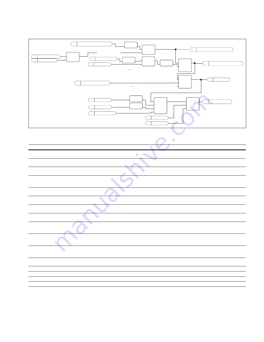
SW.B06 (Switch On Inhibited)
Internal Conditions for
Internal Conditions for Ready To Operate
Internal Conditions for Pulses Enabled
Ready To Switch On
W
CW.B03 (Start Request)
Drive Ready State
V
No Active Fault
V
Ramp Stop
V
Quick Stop
V
Ramp Stop
V
Drive Modulating
V
V
Flux Ready
R
SW.B02 (Running)
V
RunRequest
R
R
SW.B01 (Ready To Operate)
SW.B00 (Ready To Switch On)
Brake Open
V
Drive Modulating
AND
IN 1
NOT
IN
NOT
IN
NOT
IN
NOT
IN
NOT
AND
IN
IN 1
IN 2
AND
IN 1
IN 2
IN 3
AND
IN 1
IN 2
IN 3
AND
IN 1
IN 2
IN 3
AND
IN 1
IN 2
IN 3
IN 4
AND
IN 1
IN 2
IN 2
8.2.3 FB Control word
FB Control Word
Signal
Comment
b0
ON
0>1 will reset the switch on inhibit state and bring the drive to ready run. Should be reset after fault, coast stop
(b1) and emergency stop (b2) .
b1
Coasting stop
0=Coast stop active
1=Coast stop NOT active
b2
Quick stop
0=Quick stop active
1=Quick stop NOT active
b3
Start
Normal start command
0=Stop the drive
1=Start the drive
b4
Ramp output to zero
0=Force speed ramp output to zero
1=Release speed ramp output
b5
Ramp hold
0=Hold speed ramp output
1=Release speed ramp
b6
Ramp input to zero
0=Force speed ramp input to zero
1=Release speed ramp input
b7
Fault reset
0=No action
1=Reset active faults
b8
Inching 1
Run the drive with defined constant speed
0=No action
1=Run with constant speed
b9
Inching 2
Run the drive with defined constant speed
0=No action
1=Run with constant speed
b10
Fieldbus control enable
Activate fieldbus control when P3.1 =3/Fieldbus
0=Fieldbus Control NOT active
1=Activate fieldbus control
b11
Watch dog
0>1>0>1…1 sec square wave clock. This is used to check data communication between profibus master and the
drive. Used to generate FB communication -fault.
b12
b13
b14
b15


