103
SPX advanced – description of parameters
SPX ADVANCED APPLICATION MANUAL
SVCH0203—October 2017 www.eaton.com
Code
ID
Parameter
Notes
P1.7.1.3
508
DC-Braking time at stop “Stop D-BrakeTm”
50 %
0 %
fn
Output frequency
Restart
delay
DC-Brake
time at stop
50 %
DC-Brake
time at stop
100 %
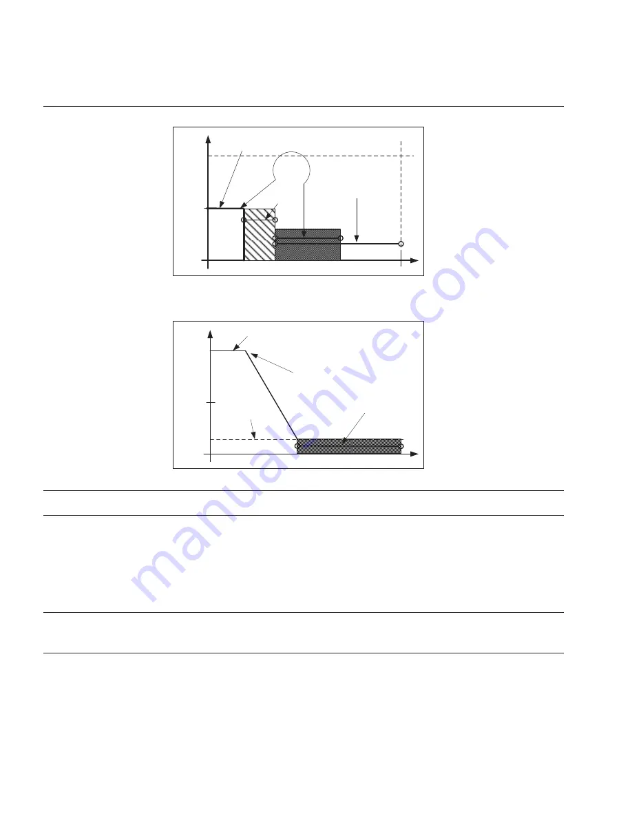
The braking time is defined with parameter DC braking time at stop. If high inertia
exists, it is recommended to use an external braking resistor for faster deceleration.
See Figure 5-14 .
50 %
0 %
fn
Output frequency
Stop
command
DC-
Brake
Freq.
DC-Brake
time at
stop
Figure 5-14 . DC-braking time when stotop mode = Ramp
P1.7.1.4
515
DC Braking frequency at stop “Stop D-BrakeFr”
The output frequency at which the DC braking is applied when making ramping stop.
P1.7.1.5
400
Scaling of DC-braking current “DC-currnt Sclng”
The DC braking current can be reduced with the free analog input signal between zero
current and the current set with parameter DC Braking Current.
0 = Not used
1 = AI1
2 = AI2
3 = AI3
4 = AI4
5 = FB Limit Scaling ID46 Monitoring value
P1.7.1.6
1080
DC Brake current in stop “DCBrakeCurlnStop”
Defines the current injected to the motor in stop state when the digital input signal
“DC Brake Command” is used to activate the DC brake when no run request is active.
When the DC brake is activated the drive will indicate being in Run state.


