6/ Repair Procedures
1503-0151-000
5/26/0
6-33
6.8. Gas Inlet Valve Repair
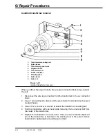
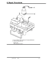
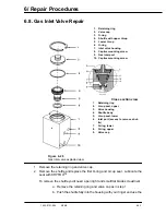
Figure 6-28
Gas inlet valve exploded view
1. Remove the retaining ring and valve cap.
2. Remove the shuttle and replace the first O-ring and U-cup seal. Lubricate the
seal with KRYTOX
™
.
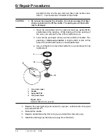
To remove the shuttle you'll need a pen light and small flat blade screwdriver.
a. Remove the retaining ring and valve cap as in step 1.
b. Push the shuttle fully into the housing with your finger and use the
Cross section view
1.
Retaining ring
2.
U-cup seal, upper
3.
Valve housing
4.
Shuttle body
5.
U-cup seal, lower
6.
Inlet port (access to remove shut-
tle)
7.
O-ring, lower
8.
O-ring, upper
9.
Valve cap
1.
Retaining ring
2.
Valve cap
3.
O-ring
4.
Shuttle with upper U-cup
5 Lower
U-cup
6.
O-ring
7.
Inlet valve housing
8.
Captive mounting screw
9.
Gas inlet port
10. Captive mounting screw
Содержание Aestiva 7900 SmartVent
Страница 2: ...1503 0151 000 3 27 97 ...
Страница 4: ...1503 0151 000 3 27 97 ...
Страница 12: ...Notes viii 1503 0151 000 3 27 97 ...
Страница 18: ...1 Introduction 1 6 1503 0151 000 5 26 0 Notes ...
Страница 44: ...2 Theory of Operation 2 26 1503 0151 000 3 27 97 Notes ...
Страница 46: ...3 Post Service Checkout 3 2 1503 0151 000 5 26 0 Notes ...
Страница 158: ...8 Schematics 8 2 7900 Ventilator 1503 0151 000 1 97 Figure 8 1 System connection block diagram ...
Страница 159: ...8 Schematics 7900 Ventilator 1503 0151 000 1 97 8 3 Figure 8 2 SIB schematic diagram interface cable connections ...
Страница 160: ...8 Schematics 8 4 7900 Ventilator 1503 0151 000 1 97 Figure 8 3 Patient interface cable Machine side ...

