7/ Illustrated Parts List
1503-0151-000
3/27/97
7-13
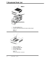
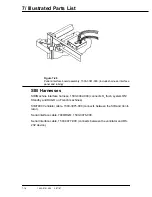
1.
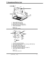
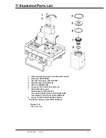
Screw M3 x 6, 9211-0430-063 (2)
2.
Pressure switch, 1503-3023-000
3.
Ground harness, 1500-7049-000
3a. Screw M4 (not shown), 0140-6226-118
3b. Washer M4 (not shown),9213-0540-003 (3)
3c. Keps nut M4 (not shown), 0144-3717-314
4.
Fitting with o-ring, 1503-3007-000 (2)
5.
Tubing (not shown), 0994-6370-010 (90 mm long 2 pieces)
5a. Coupling (not shown) 1503-3026-000
Figure 7-20
Manifold components (continued)
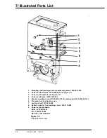
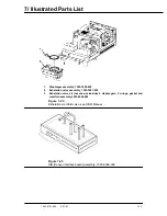
1.
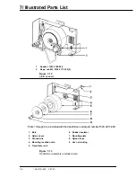
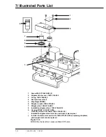
Screw M4 x 8 button head, 0140-6226-118
2.
Latch assembly service kit, 1503-8014-000
2a. Not shown, guide springs included, 1503-3029-000
3.
Test plug, 0213-4728-300
4.
O2 deflector shield, 1503-3109-000
Figure 7-21
Exhalation manifold latch assembly
1
2
3
4
1
2
3
4
Содержание Aestiva 7900 SmartVent
Страница 2: ...1503 0151 000 3 27 97 ...
Страница 4: ...1503 0151 000 3 27 97 ...
Страница 12: ...Notes viii 1503 0151 000 3 27 97 ...
Страница 18: ...1 Introduction 1 6 1503 0151 000 5 26 0 Notes ...
Страница 44: ...2 Theory of Operation 2 26 1503 0151 000 3 27 97 Notes ...
Страница 46: ...3 Post Service Checkout 3 2 1503 0151 000 5 26 0 Notes ...
Страница 158: ...8 Schematics 8 2 7900 Ventilator 1503 0151 000 1 97 Figure 8 1 System connection block diagram ...
Страница 159: ...8 Schematics 7900 Ventilator 1503 0151 000 1 97 8 3 Figure 8 2 SIB schematic diagram interface cable connections ...
Страница 160: ...8 Schematics 8 4 7900 Ventilator 1503 0151 000 1 97 Figure 8 3 Patient interface cable Machine side ...

