6/ Repair Procedures
6-24
1503-0151-000
5/26/0
6.6. Replacing the isolation transformer
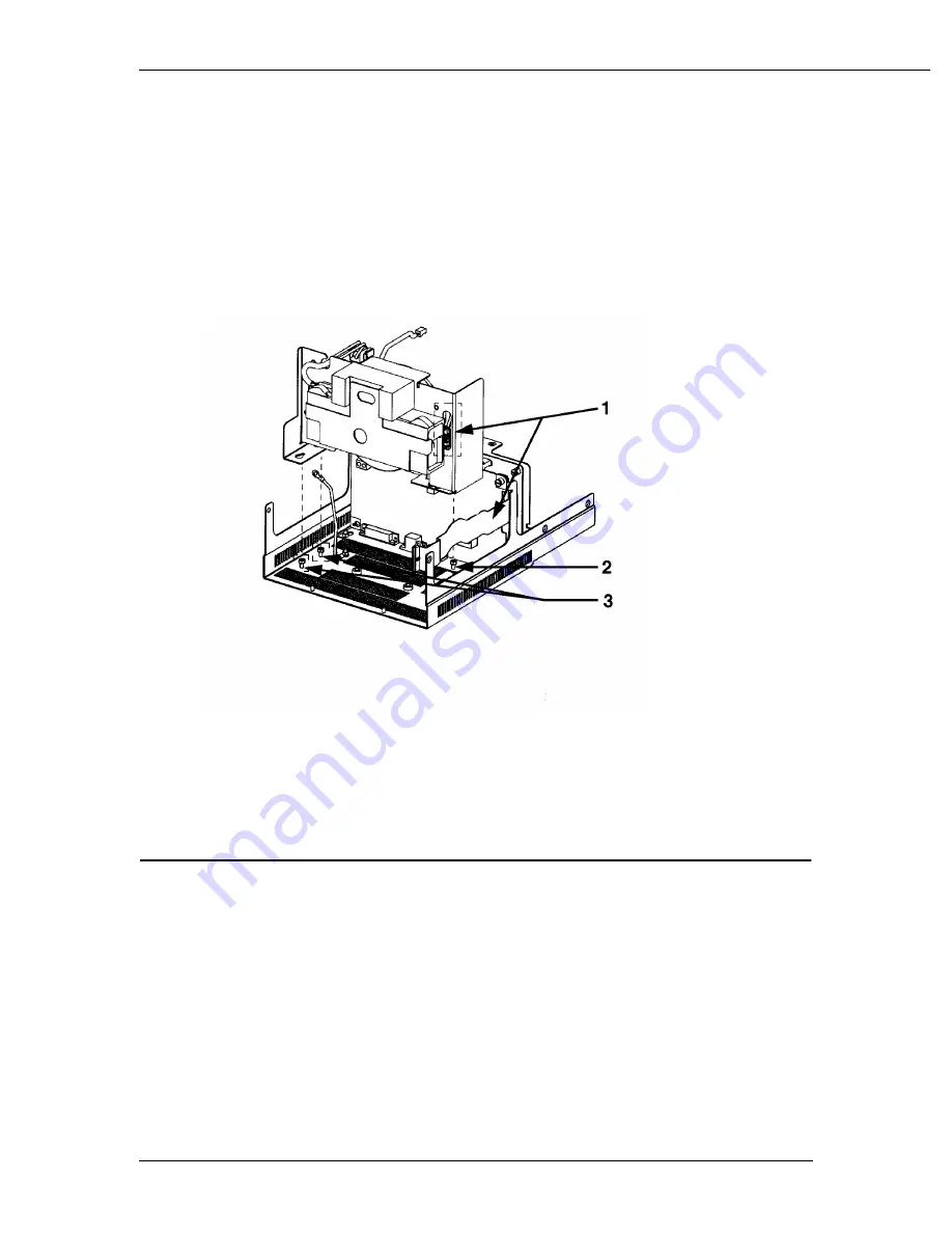
Removing the power module
1. Disconnect the ribbon cable from the front panel. Squeeze the locking tabs on
the connector.
2. Disconnect the alarm speaker cable from the microcontroller board.
3. Disconnect the isolation transformer cable from the power supply board.
4. If not already disconnected, disconnect the battery cable.
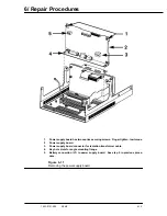
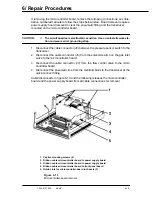
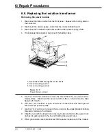
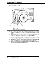
1. Route ribbon cable through the slot in chassis
2. Hex nut mounting on stud
3. Hex nut mounting on studs
Figure 6-19
Power Module removal
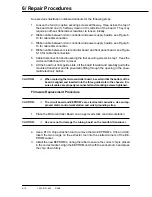
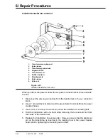
5. Use the 1.5 mm hex wrench to remove the screws from the a-c power cord re-
taining clamp. Disconnect the power cord from the a-c inlet connector. (See
figure 6-20, item 5)
6. Use the 7 mm nut driver or open end wrench to disconnect the three ground
wires from the power module.
7. Use the 7 mm nut driver to loosen the hex nuts on the angle brackets holding
the power module to the chassis.
8. Align the nuts with the larger hole in the key hole slot and slide the power mod-
ule back to gain access to the hex nut holding the ground wires.
9. When ground wires are disconnected, lift the power module out of the chassis.
Содержание Aestiva 7900 SmartVent
Страница 2: ...1503 0151 000 3 27 97 ...
Страница 4: ...1503 0151 000 3 27 97 ...
Страница 12: ...Notes viii 1503 0151 000 3 27 97 ...
Страница 18: ...1 Introduction 1 6 1503 0151 000 5 26 0 Notes ...
Страница 44: ...2 Theory of Operation 2 26 1503 0151 000 3 27 97 Notes ...
Страница 46: ...3 Post Service Checkout 3 2 1503 0151 000 5 26 0 Notes ...
Страница 158: ...8 Schematics 8 2 7900 Ventilator 1503 0151 000 1 97 Figure 8 1 System connection block diagram ...
Страница 159: ...8 Schematics 7900 Ventilator 1503 0151 000 1 97 8 3 Figure 8 2 SIB schematic diagram interface cable connections ...
Страница 160: ...8 Schematics 8 4 7900 Ventilator 1503 0151 000 1 97 Figure 8 3 Patient interface cable Machine side ...

