6/ Repair Procedures
6-32
1503-0151-000
5/26/0
Removing the solenoid and gas inlet valve assembly
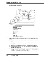
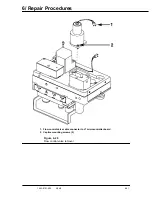
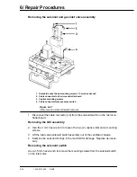
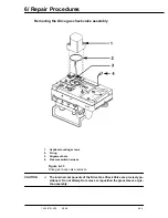
1. Solenoid socket head mounting screws 1.5 mm hex wrench
2. Cable connector to J6 microcontroller board
3. Captive mounting screws
4. Cable connector from pressure switch
Figure 6-27
Inlet valve and solenoid switch removal
1. Disconnect the cable connector (J6) from the solenoid switch on the microcon-
troller board.
Removing the GIV assembly
2. Use the 3 mm hex wrench to loosen the two (2) captive inlet valve mounting
screws.
3. Lift the inlet valve/solenoid switch assembly out of the ventilator chassis.
4. Examine the seat and O-rings in the manifold for damage. Replace as neces-
sary.
Removing the solenoid switch
Use a 1.5 mm hex wrench to remove the mounting screws from the solenoid switch
on the inlet valve.
Содержание Aestiva 7900 SmartVent
Страница 2: ...1503 0151 000 3 27 97 ...
Страница 4: ...1503 0151 000 3 27 97 ...
Страница 12: ...Notes viii 1503 0151 000 3 27 97 ...
Страница 18: ...1 Introduction 1 6 1503 0151 000 5 26 0 Notes ...
Страница 44: ...2 Theory of Operation 2 26 1503 0151 000 3 27 97 Notes ...
Страница 46: ...3 Post Service Checkout 3 2 1503 0151 000 5 26 0 Notes ...
Страница 158: ...8 Schematics 8 2 7900 Ventilator 1503 0151 000 1 97 Figure 8 1 System connection block diagram ...
Страница 159: ...8 Schematics 7900 Ventilator 1503 0151 000 1 97 8 3 Figure 8 2 SIB schematic diagram interface cable connections ...
Страница 160: ...8 Schematics 8 4 7900 Ventilator 1503 0151 000 1 97 Figure 8 3 Patient interface cable Machine side ...

