5/Maintenance
1503-0151-000
5/26/0
5-1
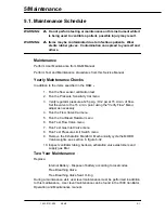
5.1. Maintenance Schedule
WARNING:
w
w
w
w
Do not perform testing or maintenance on this instrument while it
is being used to ventilate a patient, possible injury may result.
WARNING:
w
w
w
w
Items may be contaminated due to infectious patients. Wear
sterile rubber gloves. Contamination can spread to yourself and
others.
Maintenance
Perform User Maintenance from O&M Manual
Perform Test and Maintenance procedures from this Service Manual
Yearly Maintenance Checks
In addition to the items specified in the O&M --
1. Run the flow sensor calibration test
2. Run the Pressure Sensitivity Cal menu
3. Verify regulator pressure at 25 psig.
±
0.2 psi at 15 L/min. of flow.
Set the valve to the 15 L/min. point using the "Verify Flow" Menu;
adjust as necessary
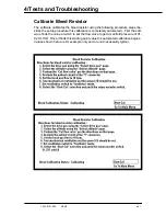
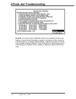
4. Run the Flow Valve Cal menu
5. Run the Cal Bleed Resistor menu
6. Run Test Flow Valve menu
7. Run Test Gas Inlet Valve menu
8. Run Test Pressure Limit Switch menu
9. Remove the Exhalation Manifold. Mechanically cycle the MOBO
Valve weights, see section 6, figure 6-32
10. Inspect ventilator tubing, bellows, exhalation valve elastomers and
supply gas filter
Two Year Maintenance
Replace:
Internal Battery - Dispose of battery according to local codes
Free Breathing Valve
Free Breathing Valve Seat O-ring
During a maintenance visit, user level maintenance must be performed in addition
to this maintenance. User level maintenance can be found in the 7900 Ventilator,
Operation and Maintenance manual.
Содержание Aestiva 7900 SmartVent
Страница 2: ...1503 0151 000 3 27 97 ...
Страница 4: ...1503 0151 000 3 27 97 ...
Страница 12: ...Notes viii 1503 0151 000 3 27 97 ...
Страница 18: ...1 Introduction 1 6 1503 0151 000 5 26 0 Notes ...
Страница 44: ...2 Theory of Operation 2 26 1503 0151 000 3 27 97 Notes ...
Страница 46: ...3 Post Service Checkout 3 2 1503 0151 000 5 26 0 Notes ...
Страница 158: ...8 Schematics 8 2 7900 Ventilator 1503 0151 000 1 97 Figure 8 1 System connection block diagram ...
Страница 159: ...8 Schematics 7900 Ventilator 1503 0151 000 1 97 8 3 Figure 8 2 SIB schematic diagram interface cable connections ...
Страница 160: ...8 Schematics 8 4 7900 Ventilator 1503 0151 000 1 97 Figure 8 3 Patient interface cable Machine side ...

