6/ Repair Procedures
6-44
1503-0151-000
5/26/0
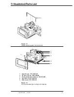
1.
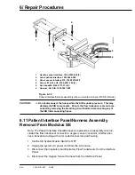
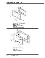
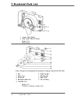
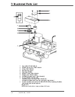
Handle, sensor interface, 1002-3952-000 (2)
2.
Label, patient interface, 1001-3464-000
3.
Panel, sensor interface 210, 1002-3970-000
4.
Screw, # 10-32 x 3/8, 0140-6231-106 (4)
5.
Nut, keps M4, 0144-3717-314 (2)
6.
Harness, SA, SIB, 1503-3081-000
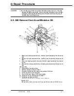
Figure 6-36
Patient interface/harness assembly (shown mounted on Excel 210 SE left side)
CAUTION:
w
Do not disconnect the hoses while the SIB is under pressure. This may
damage the SIB components. Ensure the flow transducers are not pres-
surized by removing the breathing circuit before disconnecting any of
the SIB interconnecting hoses.
6.11 Patient Interface Panel/Harness Assembly
Removal From Modulus SE
Note: The Patient Interface Panel/Harness is replaced as an assembly which in-
cludes the flow transducer connectors, oxygen sensor connector, interface har-
ness, transducer tubing with color coded connectors and housing.
1. Set the SE System Master Switch to OFF.
2. Unplug the system AC power cord from the AC source.
3. Disconnect the Inspiratory and Expiratory Flow Transducers from the Interface
Panel.
4. Disconnect the Oxygen Sensor Harness from the Interface Panel.
AA.72214
1
2
3
4
5
6
Содержание Aestiva 7900 SmartVent
Страница 2: ...1503 0151 000 3 27 97 ...
Страница 4: ...1503 0151 000 3 27 97 ...
Страница 12: ...Notes viii 1503 0151 000 3 27 97 ...
Страница 18: ...1 Introduction 1 6 1503 0151 000 5 26 0 Notes ...
Страница 44: ...2 Theory of Operation 2 26 1503 0151 000 3 27 97 Notes ...
Страница 46: ...3 Post Service Checkout 3 2 1503 0151 000 5 26 0 Notes ...
Страница 158: ...8 Schematics 8 2 7900 Ventilator 1503 0151 000 1 97 Figure 8 1 System connection block diagram ...
Страница 159: ...8 Schematics 7900 Ventilator 1503 0151 000 1 97 8 3 Figure 8 2 SIB schematic diagram interface cable connections ...
Страница 160: ...8 Schematics 8 4 7900 Ventilator 1503 0151 000 1 97 Figure 8 3 Patient interface cable Machine side ...

