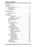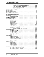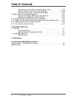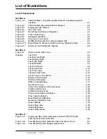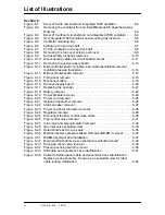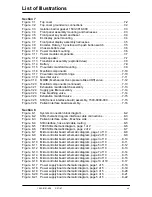
Table of Contents
1503-0151-000
3/27/97
iii
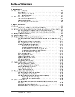
5/ Maintenance
5.1. Maintenance Schedule . . . . . . . . . . . . . . . . . . . . . . . . . . . . . . . . . . . . . . . . . . . .5-1
Maintenance . . . . . . . . . . . . . . . . . . . . . . . . . . . . . . . . . . . . . . . . . . . . . . .5-1
Yearly Maintenance Checks . . . . . . . . . . . . . . . . . . . . . . . . . . . . . . . . . . .5-1
Two Year Maintenance . . . . . . . . . . . . . . . . . . . . . . . . . . . . . . . . . . . . . . .5-1
5.2. Maintenance Procedures . . . . . . . . . . . . . . . . . . . . . . . . . . . . . . . . . . . . . . . . . . .5-2
Exhalation Valve Maintenance . . . . . . . . . . . . . . . . . . . . . . . . . . . . . . . . .5-2
Supply Gas Inlet Filter . . . . . . . . . . . . . . . . . . . . . . . . . . . . . . . . . . . . . . . .5-2
Free Breathing Valve Maintenance . . . . . . . . . . . . . . . . . . . . . . . . . . . . . .5-3
6/ Repair Procdures
6.1.General
. . . . . . . . . . . . . . . . . . . . . . . . . . . . . . . . . . . . . . . . . . . . . . . . . . . . . . .6-1
Assemblies -- tools for removal and installation . . . . . . . . . . . . . . . . . . . .6-1
6.2. Removing the 7900 ventilator from the Ohmeda Excel/Modulus SE Gas Machine 6-2
Removing the 7900 ventilator from the integrated machine . . . . . . . . . . .6-2
Removing the 7900 ventilator from the non-integrated machine . . . . . . . .6-4
6.3. Setting up the Service Shelf . . . . . . . . . . . . . . . . . . . . . . . . . . . . . . . . . . . . . . . . .6-7
6.4. Removing the top cover . . . . . . . . . . . . . . . . . . . . . . . . . . . . . . . . . . . . . . . . . . . .6-9
6.5. Printed circuit board and power module removal . . . . . . . . . . . . . . . . . . . . . . . .6-11
Removing the Power Supply circuit board and the Microcontroller circuit
board . . . . . . . . . . . . . . . . . . . . . . . . . . . . . . . . . . . . . . . . . . . . . . . . . . . .6-11
Removing Power Supply circuit board . . . . . . . . . . . . . . . . . . . . . . . . . .6-11
Removing Microcontroller circuit board . . . . . . . . . . . . . . . . . . . . . . . . . .6-14
Firmware Replacement Procedure . . . . . . . . . . . . . . . . . . . . . . . . . . . . .6-16
Software Upload Procedure . . . . . . . . . . . . . . . . . . . . . . . . . . . . .6-17
Ohmeda Software Upgrade Tool . . . . . . . . . . . . . . . . . . . . . . . . .6-17
To Install Ohmeda Software Upgrade Tool . . . . . . . . . . . . . . . . .6-17
To Install 7900 Software Field Upgrade . . . . . . . . . . . . . . . . . . . .6-18
To Perform Software Upgrade . . . . . . . . . . . . . . . . . . . . . . . . . . .6-18
Microcontroller board . . . . . . . . . . . . . . . . . . . . . . . . . . . . . . . . . . . . . . . .6-18
Removing the front panel . . . . . . . . . . . . . . . . . . . . . . . . . . . . . . . . . . . .6-19
Replacing the display board . . . . . . . . . . . . . . . . . . . . . . . . . . . . . . . . . .6-19
Replacing the encoder switch . . . . . . . . . . . . . . . . . . . . . . . . . . . . . . . . .6-21
Removing the battery . . . . . . . . . . . . . . . . . . . . . . . . . . . . . . . . . . . . . . .6-22
Testing After Maintenance . . . . . . . . . . . . . . . . . . . . . . . . . . . . . . . . . . .6-23
6.6. Replacing the isolation transformer . . . . . . . . . . . . . . . . . . . . . . . . . . . . . . . . . .6-24
Removing the power module . . . . . . . . . . . . . . . . . . . . . . . . . . . . . . . . . 6-24
Prepare power module for removal . . . . . . . . . . . . . . . . . . . . . . . . . . . . .6-25
Isolation transformer removal . . . . . . . . . . . . . . . . . . . . . . . . . . . . . . . . .6-26
Alarm speaker removal . . . . . . . . . . . . . . . . . . . . . . . . . . . . . . . . . . . . . .6-27
Power cord inlet removal . . . . . . . . . . . . . . . . . . . . . . . . . . . . . . . . . . . . .6-28
6.7. Pneumatic subassembly removal . . . . . . . . . . . . . . . . . . . . . . . . . . . . . . . . . . .6-29
Removing the non-relieving regulator . . . . . . . . . . . . . . . . . . . . . . . . . . .6-29
Removing the flow control valve . . . . . . . . . . . . . . . . . . . . . . . . . . . . . . .6-30
Removing the solenoid and gas inlet valve assembly . . . . . . . . . . . . . . .6-32
Removing the GIV assembly . . . . . . . . . . . . . . . . . . . . . . . . . . . .6-32
Removing the solenoid switch . . . . . . . . . . . . . . . . . . . . . . . . . . .6-32
6.8. Gas Inlet Valve Repair . . . . . . . . . . . . . . . . . . . . . . . . . . . . . . . . . . . . . . . . . . . .6-33
Removing the Mechanical Over-pressure Bleed Off valve (MOBO)
assembly . . . . . . . . . . . . . . . . . . . . . . . . . . . . . . . . . . . . . . . . . . . . . . . . .6-35
MOBO removal (See figure 6-30) . . . . . . . . . . . . . . . . . . . . . . . . . . . . . .6-36
MOBO installation and low pressure operation check . . . . . . . . . . . . . .6-36
Содержание Aestiva 7900 SmartVent
Страница 2: ...1503 0151 000 3 27 97 ...
Страница 4: ...1503 0151 000 3 27 97 ...
Страница 12: ...Notes viii 1503 0151 000 3 27 97 ...
Страница 18: ...1 Introduction 1 6 1503 0151 000 5 26 0 Notes ...
Страница 44: ...2 Theory of Operation 2 26 1503 0151 000 3 27 97 Notes ...
Страница 46: ...3 Post Service Checkout 3 2 1503 0151 000 5 26 0 Notes ...
Страница 158: ...8 Schematics 8 2 7900 Ventilator 1503 0151 000 1 97 Figure 8 1 System connection block diagram ...
Страница 159: ...8 Schematics 7900 Ventilator 1503 0151 000 1 97 8 3 Figure 8 2 SIB schematic diagram interface cable connections ...
Страница 160: ...8 Schematics 8 4 7900 Ventilator 1503 0151 000 1 97 Figure 8 3 Patient interface cable Machine side ...


