2/Theory of Operation
1503-0151-000
3/27/97
2-1
ZZZ2.1. General
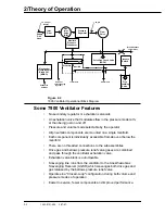
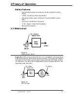
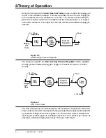
The 7900 Ventilator is a microprocessor based, electronically controlled, pneumat-
ically driven ventilator with a built in monitoring system for inspired oxygen, airway
pressure and exhaled volume. The 7900 is a "Closed Loop Control Ventilator."
Sensors in the breathing circuit are used to control and monitor patient ventilation
as well as measure inspired oxygen concentration. This allows for compensation
of compression losses, fresh gas contribution, valve and regulator drift and any
small leakage in the breathing absorber, bellows and system. User settings and
microprocessor calculations control breathing patterns. The 7900 has a user-se-
lectable Heliox mode to allow gas composition compensation when Heliox gas is
used.
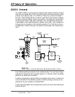
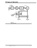
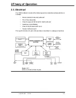
Figure 2-1
7900 Ventilator - Excel SE and Modulus SE Anesthesia System Interface.
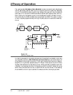
User interface settings are stored in non-volatile memory. The user may change
settings with a simple and secure setting sequence. A bellows contains breathing
gasses to be delivered to the patient
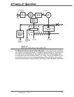
Positive End Expiratory Pressure (PEEP) is regulated electronically. Positive pres-
sure is maintained in the breathing system so that any leakage occuring is com-
pensated for by the ventilator to maintain PEEP.
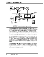
An RS-232 serial digital communications port connects to and communicates with
external devices.
SIB
Board
O2 Flush
O2 Pressure
SIB
Cable
Optional
Communications
Cable
Ventilator
Control
Module
AC Power
User Inputs
9 Soft keys,
1 knob
35 - 100 psi Suppy
Absorber
GMS
MAS
Mk5
AGSR
Gas
Scavenging
Valve
Absorber
Manifold
SIB
Interface
Panel
O2 Sensor
Flow Sensors
To Vacuum
Exhaust Gas
System
Bellows
Содержание Aestiva 7900 SmartVent
Страница 2: ...1503 0151 000 3 27 97 ...
Страница 4: ...1503 0151 000 3 27 97 ...
Страница 12: ...Notes viii 1503 0151 000 3 27 97 ...
Страница 18: ...1 Introduction 1 6 1503 0151 000 5 26 0 Notes ...
Страница 44: ...2 Theory of Operation 2 26 1503 0151 000 3 27 97 Notes ...
Страница 46: ...3 Post Service Checkout 3 2 1503 0151 000 5 26 0 Notes ...
Страница 158: ...8 Schematics 8 2 7900 Ventilator 1503 0151 000 1 97 Figure 8 1 System connection block diagram ...
Страница 159: ...8 Schematics 7900 Ventilator 1503 0151 000 1 97 8 3 Figure 8 2 SIB schematic diagram interface cable connections ...
Страница 160: ...8 Schematics 8 4 7900 Ventilator 1503 0151 000 1 97 Figure 8 3 Patient interface cable Machine side ...

