6/ Repair Procedures
1503-0151-000
5/26/0
6-37
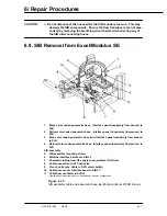
15. Install the MOBO housing cover.
16. Reinstall the bellows and ABA pop-off valve, the ABA housing and remove all
occlusions.
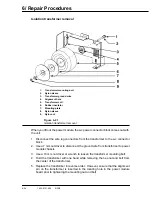
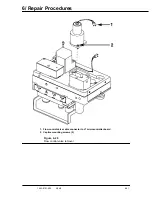
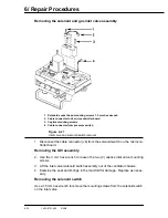
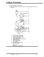
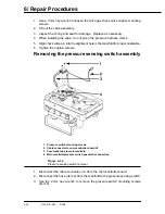
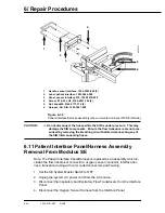
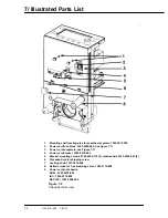
1.
MOBO installation alignment tool
2.
Cover mounting screws, 4x8 mm
3.
Top cover, no-pilot weight cylinder
4.
No-pilot weight cylinder
5.
Captive MOBO assembly mounting screws
6.
MOBO assembly body
7.
Port for no-pilot weight
8.
Port with O-ring
9.
Port for pilot weight diaphragm
10 7900 main manifold
Figure 6-31
MOBO alignment and installation
Содержание Aestiva 7900 SmartVent
Страница 2: ...1503 0151 000 3 27 97 ...
Страница 4: ...1503 0151 000 3 27 97 ...
Страница 12: ...Notes viii 1503 0151 000 3 27 97 ...
Страница 18: ...1 Introduction 1 6 1503 0151 000 5 26 0 Notes ...
Страница 44: ...2 Theory of Operation 2 26 1503 0151 000 3 27 97 Notes ...
Страница 46: ...3 Post Service Checkout 3 2 1503 0151 000 5 26 0 Notes ...
Страница 158: ...8 Schematics 8 2 7900 Ventilator 1503 0151 000 1 97 Figure 8 1 System connection block diagram ...
Страница 159: ...8 Schematics 7900 Ventilator 1503 0151 000 1 97 8 3 Figure 8 2 SIB schematic diagram interface cable connections ...
Страница 160: ...8 Schematics 8 4 7900 Ventilator 1503 0151 000 1 97 Figure 8 3 Patient interface cable Machine side ...

