4/Tests and Troubleshooting
1503-0151-000
5/26/0
4-19
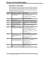
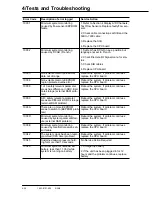
System Error Log Codes
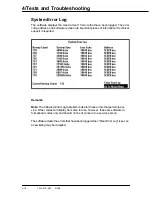
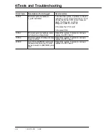
The following table of error codes are numerical in order and may be referenced
from the "System Error Log" menu displayed. Check the number on the menu and
reference this table for description and service action. Actions are numbered in a
logical action sequence. If action 1 fixes error, stop there, if action 3 fixes error
return actions 1 and 2 to previous status.
Error Code
Description of error logged
Service Action
10023
Defaults loaded to non-volatile
memory EEPROM.
1. If EEPROM or CPU board were replaced,
clear error log and reboot.
2. EEPROM failure, replace EEPROMs
3. Replace CPU board
10027
Caused by high airway pressure
above set Plimit
No Service Action required
10029
Minimum system monitoring
caused by DPL switch tripping
Reboot the system, if problem continues
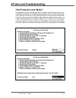
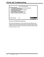
refer to Section 4, Test Press. Limit Switch
1002A
Minimum system monitoring
caused by a low battery
Charge battery, if error continues replace
battery
1002B
Minimum system monitoring
caused by incorrect flow valve
feedback
Reboot the system, if problem continues
refer to Section 4 Test Flow Valve
1002C
Minimum system monitoring
caused by incorrect GIV feedback
1. Possible bad gas inlet valve
a. Disconnect the connector to GIV at J6.
Measure ohms at approx. 25 ohms
b. If step a is unusually high or low replace
GIV solenoid
2. Replace CPU board
1002E
Minimum system monitoring
caused by battery current A/D out
of range. Battery current > 4
amperes
1. Reboot the system, if problem continues
replace the PSB (Power supply board)
2. Replace the CPU board
3. Replace battery
1002F
Minimum system monitoring
caused by battery voltage A/D out
of range. Battery voltage > 16V.
1. Reboot the system if problem continues,
measure open circuit batt voltage
2. Replace the PSB
3. Replace the CPU board
4. Replace battery
10030
Minimum system monitoring
caused by control setting change
fail
Reboot the system, if problem continues
replace the CPU board
Содержание Aestiva 7900 SmartVent
Страница 2: ...1503 0151 000 3 27 97 ...
Страница 4: ...1503 0151 000 3 27 97 ...
Страница 12: ...Notes viii 1503 0151 000 3 27 97 ...
Страница 18: ...1 Introduction 1 6 1503 0151 000 5 26 0 Notes ...
Страница 44: ...2 Theory of Operation 2 26 1503 0151 000 3 27 97 Notes ...
Страница 46: ...3 Post Service Checkout 3 2 1503 0151 000 5 26 0 Notes ...
Страница 158: ...8 Schematics 8 2 7900 Ventilator 1503 0151 000 1 97 Figure 8 1 System connection block diagram ...
Страница 159: ...8 Schematics 7900 Ventilator 1503 0151 000 1 97 8 3 Figure 8 2 SIB schematic diagram interface cable connections ...
Страница 160: ...8 Schematics 8 4 7900 Ventilator 1503 0151 000 1 97 Figure 8 3 Patient interface cable Machine side ...

