6/ Repair Procedures
6-26
1503-0151-000
5/26/0
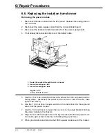
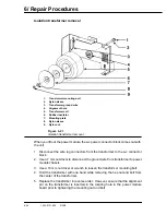
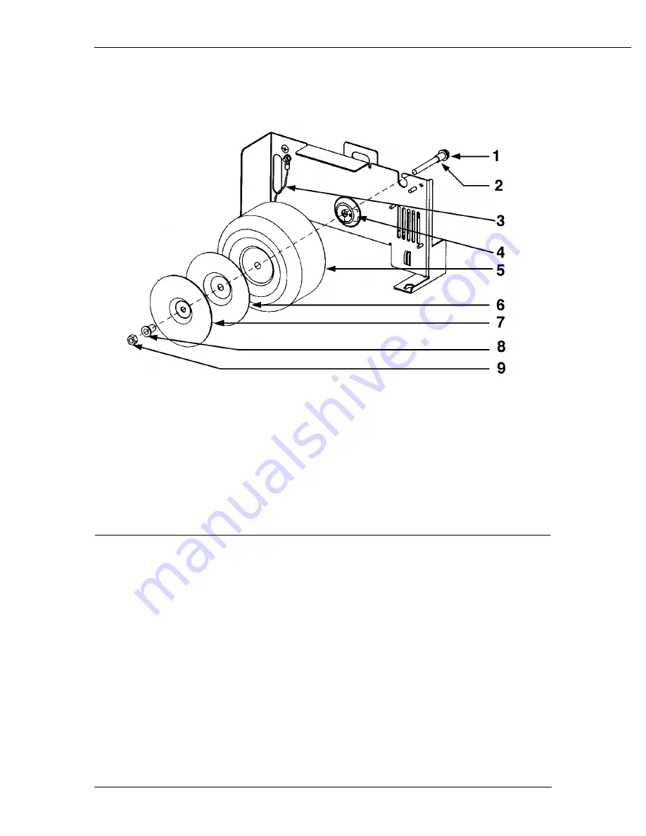
Isolation transformer removal
1.
Transformer mounting bolt
2.
Nylon sleeve
3.
Transformer ground wire
4.
Alignment hole
5.
Transformer coil
6.
Rubber insulator
7.
Mounting plate
8.
Nylon sleeve
9.
Nyloc nut
Figure 6-21
Isolation transformer removal
When you lift out the power module, the a-c power connector block comes out with
the unit.
1. Disconnect the wire lug connectors from the transformer to the a-c connector
block.
2. Use a 7 mm nut driver to disconnect the ground wire from transformer to power
module chassis.
3. Use a 10 mm nut driver or wrench to loosen the transformer mounting bolt.
4. Hold the transformer with one hand while removing the hex-nut and bolt from
the center of the transformer.
5. Replace the transformer in reverse order. However, ensure that the alignment
pin on the transformer is inserted in the locating hole in the power module
board prior to tightening the mounting nut and bolt.
Содержание Aestiva 7900 SmartVent
Страница 2: ...1503 0151 000 3 27 97 ...
Страница 4: ...1503 0151 000 3 27 97 ...
Страница 12: ...Notes viii 1503 0151 000 3 27 97 ...
Страница 18: ...1 Introduction 1 6 1503 0151 000 5 26 0 Notes ...
Страница 44: ...2 Theory of Operation 2 26 1503 0151 000 3 27 97 Notes ...
Страница 46: ...3 Post Service Checkout 3 2 1503 0151 000 5 26 0 Notes ...
Страница 158: ...8 Schematics 8 2 7900 Ventilator 1503 0151 000 1 97 Figure 8 1 System connection block diagram ...
Страница 159: ...8 Schematics 7900 Ventilator 1503 0151 000 1 97 8 3 Figure 8 2 SIB schematic diagram interface cable connections ...
Страница 160: ...8 Schematics 8 4 7900 Ventilator 1503 0151 000 1 97 Figure 8 3 Patient interface cable Machine side ...

