6/ Repair Procedures
1503-0151-000
5/26/0
6-9
6.4. Removing the top cover
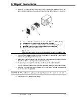
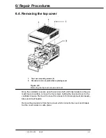
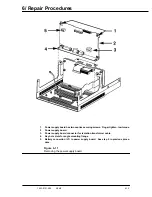
1.
Top cover mounting screws (4)
2.
Ground wire, do not pinch when replacing cover
Figure 6-8
Removing the top cover screws and cover
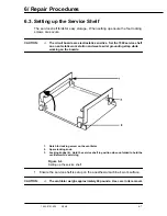
Once the ventilator is secure upon the service shelf and firmly located on the gas
machine work surface, remove the four screws holding the louvered cover to the
ventilator chassis. Remove the cover for access to the internal pneumatic assem-
blies and circuit boards.
Remove the ground wire from the top cover which connects the cover and chassis.
Set the cover aside in a safe place.
Содержание Aestiva 7900 SmartVent
Страница 2: ...1503 0151 000 3 27 97 ...
Страница 4: ...1503 0151 000 3 27 97 ...
Страница 12: ...Notes viii 1503 0151 000 3 27 97 ...
Страница 18: ...1 Introduction 1 6 1503 0151 000 5 26 0 Notes ...
Страница 44: ...2 Theory of Operation 2 26 1503 0151 000 3 27 97 Notes ...
Страница 46: ...3 Post Service Checkout 3 2 1503 0151 000 5 26 0 Notes ...
Страница 158: ...8 Schematics 8 2 7900 Ventilator 1503 0151 000 1 97 Figure 8 1 System connection block diagram ...
Страница 159: ...8 Schematics 7900 Ventilator 1503 0151 000 1 97 8 3 Figure 8 2 SIB schematic diagram interface cable connections ...
Страница 160: ...8 Schematics 8 4 7900 Ventilator 1503 0151 000 1 97 Figure 8 3 Patient interface cable Machine side ...

