6/ Repair Procedures
6-20
1503-0151-000
5/26/0
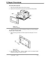
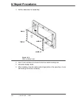
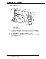
3. Set the cable aside for reassembly.
Figure 6-16
Remove display board
4. Use 5.5 mm nut driver to remove the four hex-head mounting nuts.
5. Lift out the display board.
6. When installing, check for debris and/or finger prints on the panel face. Clean
with isopropyl alcohol as necessary.
Содержание Aestiva 7900 SmartVent
Страница 2: ...1503 0151 000 3 27 97 ...
Страница 4: ...1503 0151 000 3 27 97 ...
Страница 12: ...Notes viii 1503 0151 000 3 27 97 ...
Страница 18: ...1 Introduction 1 6 1503 0151 000 5 26 0 Notes ...
Страница 44: ...2 Theory of Operation 2 26 1503 0151 000 3 27 97 Notes ...
Страница 46: ...3 Post Service Checkout 3 2 1503 0151 000 5 26 0 Notes ...
Страница 158: ...8 Schematics 8 2 7900 Ventilator 1503 0151 000 1 97 Figure 8 1 System connection block diagram ...
Страница 159: ...8 Schematics 7900 Ventilator 1503 0151 000 1 97 8 3 Figure 8 2 SIB schematic diagram interface cable connections ...
Страница 160: ...8 Schematics 8 4 7900 Ventilator 1503 0151 000 1 97 Figure 8 3 Patient interface cable Machine side ...


