6/ Repair Procedures
6-30
1503-0151-000
5/26/0
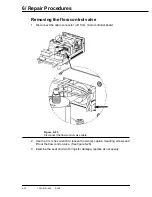
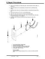
Removing the flow control valve
1. Disconnect the cable connector (J7) from microcontroller board.
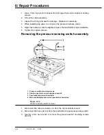
Figure 6-25
Disconnect the flow control valve cable
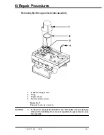
2. Use the 3 mm hex wrench to loosen the two (2) captive mounting screws and
lift out the flow control valve. (See figure 6-26)
3. Examine the seat and two O-rings for damage; replace as necessary.
Содержание Aestiva 7900 SmartVent
Страница 2: ...1503 0151 000 3 27 97 ...
Страница 4: ...1503 0151 000 3 27 97 ...
Страница 12: ...Notes viii 1503 0151 000 3 27 97 ...
Страница 18: ...1 Introduction 1 6 1503 0151 000 5 26 0 Notes ...
Страница 44: ...2 Theory of Operation 2 26 1503 0151 000 3 27 97 Notes ...
Страница 46: ...3 Post Service Checkout 3 2 1503 0151 000 5 26 0 Notes ...
Страница 158: ...8 Schematics 8 2 7900 Ventilator 1503 0151 000 1 97 Figure 8 1 System connection block diagram ...
Страница 159: ...8 Schematics 7900 Ventilator 1503 0151 000 1 97 8 3 Figure 8 2 SIB schematic diagram interface cable connections ...
Страница 160: ...8 Schematics 8 4 7900 Ventilator 1503 0151 000 1 97 Figure 8 3 Patient interface cable Machine side ...

