2/Theory of Operation
2-12
1503-0151-000
3/27/97
ac Power-On Indicato
r
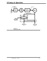
ac Step-Down Regulator and Battery Charger
The dc step-down regulator takes the output from ac/dc conversion stage (24-62
Vdc) and converts it to 16.6 Vdc. The battery charge circuit charges the sealed lead
acid battery anytime ac power is supplied.
A Schottky Diode provides uninterrupted-power-supply (UPS) function during ac-
powered to battery powered transitions. When ac power is interrupted, the switch-
over between ac and Battery is automatic. When ac power is off, this diode also
works as a reverse blocking device preventing the battery from being drained by
the regulator circuitry.
Synchronous step-down regulator
Lead acid battery charge controller
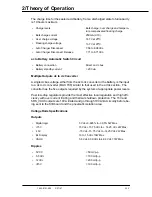
The battery charge circuit charges the sealed lead acid battery anytime ac power
is supplied. This circuit is based on the Unitrode UC3906 charger controller which
monitors and controls both the charging voltage and current through three sepa-
rate charge states:
•
a high current bulk-charge state,
•
a controlled over-charge,
and
•
a precision float-charge.
This sequence maximizes battery capacity and life while minimizing charge time.
Switch over circuitry detects the presence or loss of ac supplied power and provide
an automatic and transparent transition to AC or battery power.
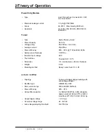
•
Type
LED
•
Color
Green
•
LED drive current
15mA.
•
Location
Display Board
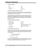
•
Power efficiency
80 - 85%
•
Input voltage range
24 - 62 Vdc
•
Switching Controller
MAX797
•
Switch devices
100V 19-28A, 0.20 / 0.07 ohm. MOS-
FETMTW 4510E / IRF540.
•
Output Ripple
Less than 200mV peak to peak
•
dc output voltage
16.6 V
Содержание Aestiva 7900 SmartVent
Страница 2: ...1503 0151 000 3 27 97 ...
Страница 4: ...1503 0151 000 3 27 97 ...
Страница 12: ...Notes viii 1503 0151 000 3 27 97 ...
Страница 18: ...1 Introduction 1 6 1503 0151 000 5 26 0 Notes ...
Страница 44: ...2 Theory of Operation 2 26 1503 0151 000 3 27 97 Notes ...
Страница 46: ...3 Post Service Checkout 3 2 1503 0151 000 5 26 0 Notes ...
Страница 158: ...8 Schematics 8 2 7900 Ventilator 1503 0151 000 1 97 Figure 8 1 System connection block diagram ...
Страница 159: ...8 Schematics 7900 Ventilator 1503 0151 000 1 97 8 3 Figure 8 2 SIB schematic diagram interface cable connections ...
Страница 160: ...8 Schematics 8 4 7900 Ventilator 1503 0151 000 1 97 Figure 8 3 Patient interface cable Machine side ...

