6/ Repair Procedures
6-14
1503-0151-000
5/26/0
Removing Microcontroller circuit board
CAUTION:
w
Disconnect the internal battery before attempting to remove or repair any
circuit board. Failure to do so may damage the internal electronics.
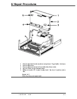
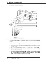
1. Pneumatic quick-connect fitting from main manifold
2. Connector from pressure sensor switch (J8)
3. Connector from GIV solenoid (J6)
4. connector from flow valve (J7)
Figure 6-12
Microcontroller board connector and cable identification around manifold pres-
sure transducer
Содержание Aestiva 7900 SmartVent
Страница 2: ...1503 0151 000 3 27 97 ...
Страница 4: ...1503 0151 000 3 27 97 ...
Страница 12: ...Notes viii 1503 0151 000 3 27 97 ...
Страница 18: ...1 Introduction 1 6 1503 0151 000 5 26 0 Notes ...
Страница 44: ...2 Theory of Operation 2 26 1503 0151 000 3 27 97 Notes ...
Страница 46: ...3 Post Service Checkout 3 2 1503 0151 000 5 26 0 Notes ...
Страница 158: ...8 Schematics 8 2 7900 Ventilator 1503 0151 000 1 97 Figure 8 1 System connection block diagram ...
Страница 159: ...8 Schematics 7900 Ventilator 1503 0151 000 1 97 8 3 Figure 8 2 SIB schematic diagram interface cable connections ...
Страница 160: ...8 Schematics 8 4 7900 Ventilator 1503 0151 000 1 97 Figure 8 3 Patient interface cable Machine side ...

