2/Theory of Operation
2-6
1503-0151-000
3/27/97
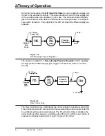
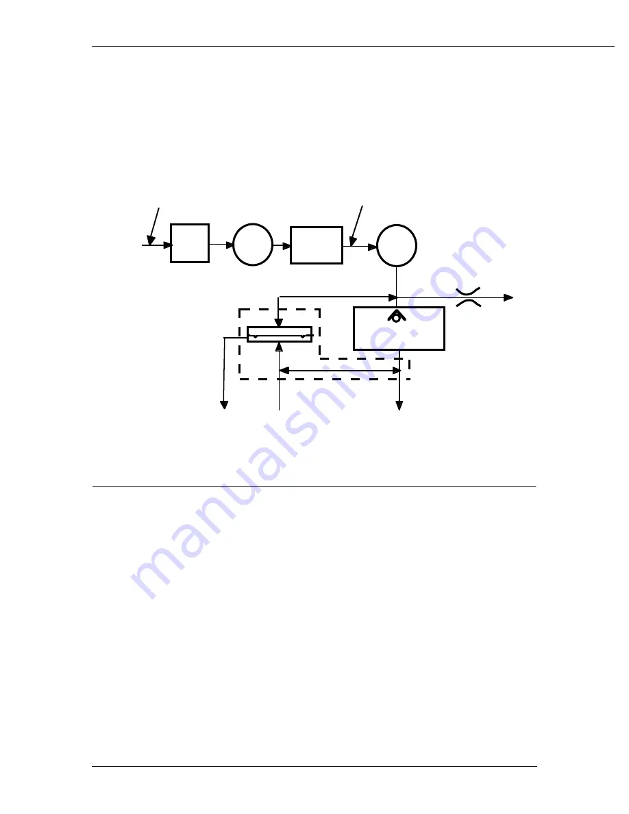
The autoclavable
Exhalation Valve Manifold
contains an elastomeric diaphragm
used in association with the flow valve to control the pressures within the breathing
circuit. The manifold contains ports for the bellows drive gas (25 mm), the bellows
return gas (17 mm) and the AGSS (Anesthesia Gas Scavenging System) (30 mm).
Pilot control of the exhalation valve is accomplished through pneumatic connec-
tions internal to the 7900 ventilator main pneumatic manifold. The valve is normal-
ly open, requiring approximately 2 cmH
2
O of pilot pressure to seal the breathing
circuit.
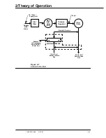
Figure 2-8
Drive Gas Check Valve
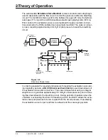
In order to generate the required pilot pressure for sealing the exhalation valve dur-
ing inspiratory periods, a
DGCV (Drive Gas Check Valve)
is used downstream of
the exhalation valve pilot connection. This valve is biased shut using an integral
weight so as to generate approximately 3.5 cmH
2
O of bias pressure prior to allow-
ing flow downstream to the breathing circuit. During periods of operation when the
ventilator is exhausting flow from the breathing circuit, the DGCV allows the exha-
lation valve pilot pressure to be de-coupled from the circuit pressure, thus allowing
the exhalation valve to open and flow to exhaust and the scavenging system.
Bleed to
Ambient
Supply
Gas
Hose
Flow
Valve
Pressure
Regulator
Inlet
Filter
Gas
Inlet
Valve
(GIV)
25 psi
Drive Gas Check Valve
(DGCV)
25 mm port
17 mm port
Exhaust
to Scavenging
System
Exhalation
Manifold
35 - 100 psi
Supply inlet
Содержание Aestiva 7900 SmartVent
Страница 2: ...1503 0151 000 3 27 97 ...
Страница 4: ...1503 0151 000 3 27 97 ...
Страница 12: ...Notes viii 1503 0151 000 3 27 97 ...
Страница 18: ...1 Introduction 1 6 1503 0151 000 5 26 0 Notes ...
Страница 44: ...2 Theory of Operation 2 26 1503 0151 000 3 27 97 Notes ...
Страница 46: ...3 Post Service Checkout 3 2 1503 0151 000 5 26 0 Notes ...
Страница 158: ...8 Schematics 8 2 7900 Ventilator 1503 0151 000 1 97 Figure 8 1 System connection block diagram ...
Страница 159: ...8 Schematics 7900 Ventilator 1503 0151 000 1 97 8 3 Figure 8 2 SIB schematic diagram interface cable connections ...
Страница 160: ...8 Schematics 8 4 7900 Ventilator 1503 0151 000 1 97 Figure 8 3 Patient interface cable Machine side ...

