6/ Repair Procedures
6-8
1503-0151-000
5/26/0
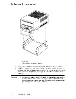
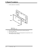
Figure 6-7
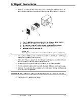
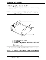
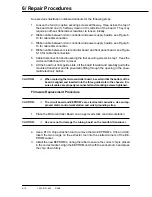
Put the ventilator on the service shelf
2. Arrange the ventilator so the rear is toward the left side of the gas machine.
3. Set the ventilator down on the service shelf so the locking screw fits below the
mounting rail. Slide ventilator toward the front on the rails so locking screw
slides in the notch. Tighten the securing knob to hold the ventilator to the ser-
vice shelf.
CAUTION:
w
The ventilator must sit on the left edge of the gas machine work surface
to clear cables and hoses. Use care to prevent the ventilator from slip-
ping off the surface and possibly causing damage to the ventilator or in-
jury to the person servicing the ventilator.
Содержание Aestiva 7900 SmartVent
Страница 2: ...1503 0151 000 3 27 97 ...
Страница 4: ...1503 0151 000 3 27 97 ...
Страница 12: ...Notes viii 1503 0151 000 3 27 97 ...
Страница 18: ...1 Introduction 1 6 1503 0151 000 5 26 0 Notes ...
Страница 44: ...2 Theory of Operation 2 26 1503 0151 000 3 27 97 Notes ...
Страница 46: ...3 Post Service Checkout 3 2 1503 0151 000 5 26 0 Notes ...
Страница 158: ...8 Schematics 8 2 7900 Ventilator 1503 0151 000 1 97 Figure 8 1 System connection block diagram ...
Страница 159: ...8 Schematics 7900 Ventilator 1503 0151 000 1 97 8 3 Figure 8 2 SIB schematic diagram interface cable connections ...
Страница 160: ...8 Schematics 8 4 7900 Ventilator 1503 0151 000 1 97 Figure 8 3 Patient interface cable Machine side ...

