6/ Repair Procedures
1503-0151-000
5/26/0
6-5
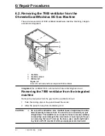
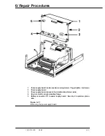
1.
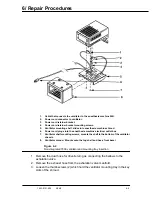
Cable that connects the ventilator to the anesthesia machine SIB.
2.
Power cord connector to ventilator.
3.
Power cord retainer bracket.
4.
Power cord retainer bracket mounting screws.
5.
Ventilator mounting shelf, slides into anesthesia machine shroud.
6.
Power cord, plugs into the anesthesia machine electrical outlet box.
7.
Ventilator shelf mounting screws, mounts the shelf to the bottom of the ventilator
chassis.
8.
Ventilator shroud. Mounts onto the top shelf and has a front bezel
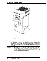
Figure 6-4
Non-integrated 7900 ventilator and mounting tray insertion
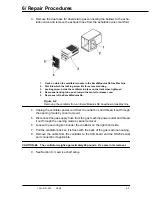
1. Remove the dual hose for drive/return gas connecting the bellows to the
exhalation valve.
2. Remove the exhaust hose from the exhalation valve manifold.
3. Loosen the thumb screws (2) which hold the ventilator mounting tray in the key
slots of the shroud.
Содержание Aestiva 7900 SmartVent
Страница 2: ...1503 0151 000 3 27 97 ...
Страница 4: ...1503 0151 000 3 27 97 ...
Страница 12: ...Notes viii 1503 0151 000 3 27 97 ...
Страница 18: ...1 Introduction 1 6 1503 0151 000 5 26 0 Notes ...
Страница 44: ...2 Theory of Operation 2 26 1503 0151 000 3 27 97 Notes ...
Страница 46: ...3 Post Service Checkout 3 2 1503 0151 000 5 26 0 Notes ...
Страница 158: ...8 Schematics 8 2 7900 Ventilator 1503 0151 000 1 97 Figure 8 1 System connection block diagram ...
Страница 159: ...8 Schematics 7900 Ventilator 1503 0151 000 1 97 8 3 Figure 8 2 SIB schematic diagram interface cable connections ...
Страница 160: ...8 Schematics 8 4 7900 Ventilator 1503 0151 000 1 97 Figure 8 3 Patient interface cable Machine side ...

