7/ Illustrated Parts List
1503-0151-000
3/27/97
7-7
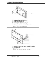
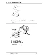
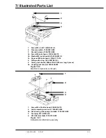
1.
Keps nut M4, 0144-3717-314 (3)
2.
Ground harness, 1500-7048-000
2a. Keps nut (not shown), 0144-3717-314 (2)
2b. Washer M4 (not shown), 9213-0540-003 (2)
3.
Label set, 1503-3027-000
Figure 7-10
Power module mounting
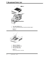
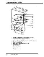
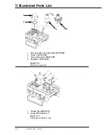
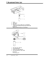
1.
Connector, AC inlet 1503-3000-000
1a. Fuse 2 amp 250V 5x20 mm delayed time (not shown), 1503-3073-000 (2)
2.
Filter harness, 1500-7053-000
2a. Keps nut M4 (not shown), 0144-3717-314
2b. Washer M4 (not shown), 9213-0540-003
3.
Transformer assembly, 1503-3017-000, see Figure 7-13
4.
Bracket power module, 1503-3060-000
Figure 7-11
Power module components
3
2
1
1
2
3
4
Содержание Aestiva 7900 SmartVent
Страница 2: ...1503 0151 000 3 27 97 ...
Страница 4: ...1503 0151 000 3 27 97 ...
Страница 12: ...Notes viii 1503 0151 000 3 27 97 ...
Страница 18: ...1 Introduction 1 6 1503 0151 000 5 26 0 Notes ...
Страница 44: ...2 Theory of Operation 2 26 1503 0151 000 3 27 97 Notes ...
Страница 46: ...3 Post Service Checkout 3 2 1503 0151 000 5 26 0 Notes ...
Страница 158: ...8 Schematics 8 2 7900 Ventilator 1503 0151 000 1 97 Figure 8 1 System connection block diagram ...
Страница 159: ...8 Schematics 7900 Ventilator 1503 0151 000 1 97 8 3 Figure 8 2 SIB schematic diagram interface cable connections ...
Страница 160: ...8 Schematics 8 4 7900 Ventilator 1503 0151 000 1 97 Figure 8 3 Patient interface cable Machine side ...

