6/ Repair Procedures
6-28
1503-0151-000
5/26/0
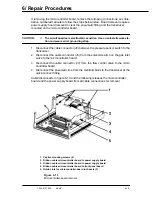
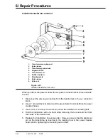
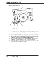
Power cord inlet removal
Figure 6-23
Power cord inlet connector removal
1. Item 1, figure 6-23 is the a-c inlet power connector where the two, 2 ampere
line fuses are located. Fuses may be replaced without removal of the inlet con-
nector.
2. Disconnect the white wire quick-connect terminal from the inlet connector as-
sembly to the transformer. (Rear connection, see figure 6-23 item 4.)
3. Disconnect the ground wire quick-connect terminal from the inlet connector as-
sembly to the ground lug on power module. (Middle connection.)
4. Disconnect the black wire quick-connect terminal from the inlet connector as-
sembly to the transformer. (front connection, see figure 6-23 item 3.)
5. Depress the locking tabs on both sides of the assembly and lift the assembly
out of the mounting hole in the power module.
Содержание Aestiva 7900 SmartVent
Страница 2: ...1503 0151 000 3 27 97 ...
Страница 4: ...1503 0151 000 3 27 97 ...
Страница 12: ...Notes viii 1503 0151 000 3 27 97 ...
Страница 18: ...1 Introduction 1 6 1503 0151 000 5 26 0 Notes ...
Страница 44: ...2 Theory of Operation 2 26 1503 0151 000 3 27 97 Notes ...
Страница 46: ...3 Post Service Checkout 3 2 1503 0151 000 5 26 0 Notes ...
Страница 158: ...8 Schematics 8 2 7900 Ventilator 1503 0151 000 1 97 Figure 8 1 System connection block diagram ...
Страница 159: ...8 Schematics 7900 Ventilator 1503 0151 000 1 97 8 3 Figure 8 2 SIB schematic diagram interface cable connections ...
Страница 160: ...8 Schematics 8 4 7900 Ventilator 1503 0151 000 1 97 Figure 8 3 Patient interface cable Machine side ...


