8 /Schematics
7900 Ventilator- 1503-0151-000 1-97
8-5
1.
Coded yellow Expiratory transducer high
2.
Coded blue Expiratory transducer low
3.
Coded black Inspiratory transducer low
4.
Patient interface cable connect
5.
SIB/7900 Vent interface cable
6.
Coded natural Inspiratory transducer high
and airway pressure monitor connect
7.
SIB assembly housing
8.
System ON/Standby switch
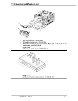
Figure 8-4
SIB interface, hose and cable routing
Содержание Aestiva 7900 SmartVent
Страница 2: ...1503 0151 000 3 27 97 ...
Страница 4: ...1503 0151 000 3 27 97 ...
Страница 12: ...Notes viii 1503 0151 000 3 27 97 ...
Страница 18: ...1 Introduction 1 6 1503 0151 000 5 26 0 Notes ...
Страница 44: ...2 Theory of Operation 2 26 1503 0151 000 3 27 97 Notes ...
Страница 46: ...3 Post Service Checkout 3 2 1503 0151 000 5 26 0 Notes ...
Страница 158: ...8 Schematics 8 2 7900 Ventilator 1503 0151 000 1 97 Figure 8 1 System connection block diagram ...
Страница 159: ...8 Schematics 7900 Ventilator 1503 0151 000 1 97 8 3 Figure 8 2 SIB schematic diagram interface cable connections ...
Страница 160: ...8 Schematics 8 4 7900 Ventilator 1503 0151 000 1 97 Figure 8 3 Patient interface cable Machine side ...

