background image

499-493

V

ERANDA

L

I

F

E

T

I

M

E


W

A

R

R

A

N

T

Y

L I F E T I M E   W A R R A N T Y

52

Содержание VERANDA 499-493

Страница 1: ...499 493 VERANDA L I F E T I M E W A R R A N T Y L I F E T I M E W A R R A N T Y 52...

Страница 2: ...peeling Brass finishes of this type give their longest useful life when protected from varying weather conditions A certain amount of wobble is normal and should not be considered a defect Servicing p...

Страница 3: ...Safety Rules Unpacking Your Fan Installing Your Fan Installing the Light Kit Your Care of Your Fan Troubleshooting Specifications Operating Transmitter 1 2 3 10 11 12 13 14 Table of Contents...

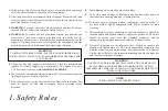
Страница 4: ...ctrical connections spliced conductors should be turned upward and pushed carefully up into the outlet box The wires should be spread apart with the grounded conductor and the equipment grounding cond...

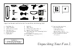
Страница 5: ...Coupling cover 6 7 Light plate 3 1 2 8 9 4 5 6 7 11 10 13 14 14 Loose partsbag containing a Mounting hardware Screws 2 PCs Lock washers 2PCs Metal washers 2PCs Plastic wire connectors 3 PCs b Blade at...

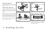
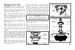
Страница 6: ...ers Secure the outlet box directly to the building structure Use appropriate fasteners and building materials The outlet box and its support must be able to fully support the moving weight of the fan...

Страница 7: ...e them onto the new longer downrod before proceeding step 6 The longer downrod is available at any Home Depot store WARNING FAILURE TO PROPERLY INSTALL LOCKING PIN AS NOTED INSTEP 7 COULD RESULT IN FA...

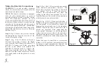
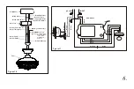
Страница 8: ...om the fan to the Blue wire marked For Light from the receiver Secure wire connections with the plastic wire nuts provided Step 3 Fig 10 11 Receiver to house supply wires electrical connections Connec...

Страница 9: ...reen Green INPUT AC120V AC SUPPLY 6 Figure 10 White neutral White neutral Green or bare copper ground White AC IN N White to motor N Ground green Connect to ground wire on hanger bracket if no house g...

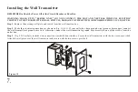
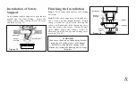
Страница 10: ...ox Secure thewall transmitter withthe two screwsprovided Attach the wallplate over thewall transmitter andsecure with thetwo screws provided Make the electrical connections as shown in If your outlet...

Страница 11: ...and rotate clockwise until tight Note adjust the canopy screws as necessary until the canopy and canopy cover are snug Fig 14 WARNING Make sure thenotch on thehanging bracket properly sits inthe groo...

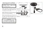
Страница 12: ...ght Fig 16 blade Repeat steps for the remaining blades Step 3 Fasten the blade arms to the motor by inserting the tab from the blade arms to the slot in the bottom motor housing then tighten the two s...

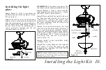
Страница 13: ...urn light kit until it locks in place at the narrow section of the key holes Secure by tightening the 2 screws previously l o o s e n e d a n d t h e o n e p r e v i o u s l y removed Fig 19 Step 4 In...

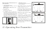
Страница 14: ...the power Off and On to the Fan andLight s The Reverse switch is located on the top of motor housing Slide the switch to the Left for warm weather operation Slide the switch to the Rightfor cool weath...

Страница 15: ...finish The plating is s e a l e d w i t h a l a c q u e r t o m i n i m i z e discoloration or tarnishing Do not use water when cleaning This could damage the motor or the wood or possibly cause an e...

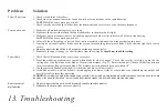
Страница 16: ...e the uppercanopy is a short distancefrom the ceiling It should not touch the ceiling the Do not connect the fanwith a wall mounted variablespeed control s 1 Do not connect thefan with a wall mountedv...

Страница 17: ...y do not include Amps andWattage used by the light kit RPM CFM N W G W C F 52 120 xx Xx kgs Xx kgs Xxx Xx Xx Xxxx 120 120 Fan Size Speed Volts Amps Watts Low Medium High Distributed by Home Depot ofCa...

Отзывы: