6/ Repair Procedures
6-6
1503-0151-000
5/26/0
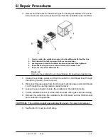
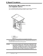
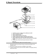
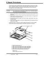
4. Slide the mounting tray and ventilator out the rear of the shroud far enough to
access the power cord and supply gas hose.
5. Disconnect the gas supply hose.
6. Remove the two mounting screws; remove the bracket and power cord.
7. Disconnect the cable from the ventilator that goes to the SIB in the machine.
CAUTION:
w
The ventilator weighs approximately 40 pounds. Use care in its removal.
8. Remove the 7900 Ventilator and mounting tray from the anesthesia machine.
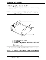
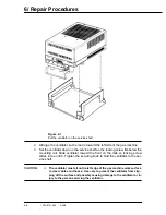
9. It is necessary to remove the mounting tray to set the ventilator on the service
shelf. Remove the three mounting screws from the tray.
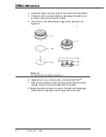
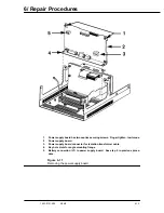
10. See service shelf setup
1.
Threaded nut for thumb screw lock bolt - one on each side of tray
2.
Threaded nut for shipping screw
3.
Locating pins to center and locate the ventilator properly
4.
Clearance holes for tray mounting to ventilator chassis
Figure 6-5
Ventilator mounting tray
Содержание Aestiva 7900 SmartVent
Страница 2: ...1503 0151 000 3 27 97 ...
Страница 4: ...1503 0151 000 3 27 97 ...
Страница 12: ...Notes viii 1503 0151 000 3 27 97 ...
Страница 18: ...1 Introduction 1 6 1503 0151 000 5 26 0 Notes ...
Страница 44: ...2 Theory of Operation 2 26 1503 0151 000 3 27 97 Notes ...
Страница 46: ...3 Post Service Checkout 3 2 1503 0151 000 5 26 0 Notes ...
Страница 158: ...8 Schematics 8 2 7900 Ventilator 1503 0151 000 1 97 Figure 8 1 System connection block diagram ...
Страница 159: ...8 Schematics 7900 Ventilator 1503 0151 000 1 97 8 3 Figure 8 2 SIB schematic diagram interface cable connections ...
Страница 160: ...8 Schematics 8 4 7900 Ventilator 1503 0151 000 1 97 Figure 8 3 Patient interface cable Machine side ...

