4/Tests and Troubleshooting
4-38
1503-0151-000
5/26/0
4.7. Troubleshooting Guides
Some ventilator problems may not generate any ventilator messages, even though
the ventilator may not be functioning correctly.
Operational alarm messages are found in the Operation and Maintenance manual.
Actions are numbered in a logical action sequence. If action 1 fixes error, stop
there, if action 3 fixes error return actions 1 and 2 to previous status.
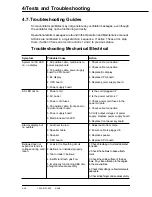
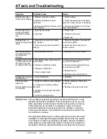
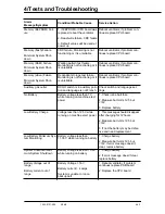
Troubleshooting Mechanical/Electrical
Symptom
Probable Cause
Action
System on/AC LED
on, no display
1. 50 position cable, membrane to
power supply board
2. 18 position cable, power supply
board to CPU board
3. EL display
4. CPU board
5. Power supply board
1. Check cable connection
2. Check cable connection
3. Replace EL display
4. Replace CPU board
5. Replace power supply board
AC LED not on
1. Power cord
2. AC power
3. Power cord fuses
4. 50 position cable, front panel to
microcontroller board
5. Power supply board
6. Membrane switch LED
1. Is the cord plugged in?
2. Is the power outlet o.k.?
3. Check power cord fuses in the
power module
4. Check cable connection
5. Verify output voltages of power
supply. Replace power supply board
6. Replace front panel keyboard
Alarms display, but
no audible
1. Audio set too low
2. Speaker cable
3. Speaker
4. CPU board
1. Adjust audio from menu
2. Ensure cable is plugged in
3. Replace speaker
4. Replace CPU board
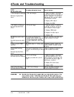
Bellows does not
expand or tends to
collapse during venti-
lation.
1. Leak in the breathing circuit.
2. Bellows not installed properly.
3. Tear or leak in bellows.
4. Insufficient fresh gas flow.
5. Improperly functioning ABA dia-
phragm and seat assembly.
1. Check breathing circuit and absorber
for leaks.
2. Check the bellows to base attach-
ment.
3. Check the entire surface of the bel-
lows. Pay close attention to the angles
in the convolutions.
4. Check that settings on flowmeters are
adequate.
5. Check diaphragm and seat assembly.
Содержание Aestiva 7900 SmartVent
Страница 2: ...1503 0151 000 3 27 97 ...
Страница 4: ...1503 0151 000 3 27 97 ...
Страница 12: ...Notes viii 1503 0151 000 3 27 97 ...
Страница 18: ...1 Introduction 1 6 1503 0151 000 5 26 0 Notes ...
Страница 44: ...2 Theory of Operation 2 26 1503 0151 000 3 27 97 Notes ...
Страница 46: ...3 Post Service Checkout 3 2 1503 0151 000 5 26 0 Notes ...
Страница 158: ...8 Schematics 8 2 7900 Ventilator 1503 0151 000 1 97 Figure 8 1 System connection block diagram ...
Страница 159: ...8 Schematics 7900 Ventilator 1503 0151 000 1 97 8 3 Figure 8 2 SIB schematic diagram interface cable connections ...
Страница 160: ...8 Schematics 8 4 7900 Ventilator 1503 0151 000 1 97 Figure 8 3 Patient interface cable Machine side ...

