6/ Repair Procedures
1503-0151-000
5/26/0
6-11
6.5. Printed circuit board and power module
removal
Removing the Power Supply circuit board and the Microcontroller
circuit board
Note:
To remove the microcontroller circuit board you first must remove the
power supply circuit board.
Removing Power Supply circuit board
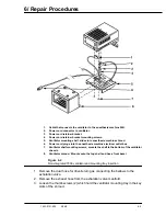
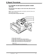
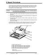
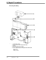
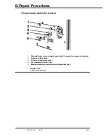
1. Battery cable connector (J1)
2. Alarm speaker connector to microcontroller board (J1)
3. Ribbon cable microcontroller board to power supply board (J2)
4. Ribbon cable microcontroller board to power supply board (J3)
5. Ribbon cable microcontroller board to front panel board (J5)
Figure 6-10
Disconnecting cables for circuit board removal
Содержание Aestiva 7900 SmartVent
Страница 2: ...1503 0151 000 3 27 97 ...
Страница 4: ...1503 0151 000 3 27 97 ...
Страница 12: ...Notes viii 1503 0151 000 3 27 97 ...
Страница 18: ...1 Introduction 1 6 1503 0151 000 5 26 0 Notes ...
Страница 44: ...2 Theory of Operation 2 26 1503 0151 000 3 27 97 Notes ...
Страница 46: ...3 Post Service Checkout 3 2 1503 0151 000 5 26 0 Notes ...
Страница 158: ...8 Schematics 8 2 7900 Ventilator 1503 0151 000 1 97 Figure 8 1 System connection block diagram ...
Страница 159: ...8 Schematics 7900 Ventilator 1503 0151 000 1 97 8 3 Figure 8 2 SIB schematic diagram interface cable connections ...
Страница 160: ...8 Schematics 8 4 7900 Ventilator 1503 0151 000 1 97 Figure 8 3 Patient interface cable Machine side ...

