168
Commander SE Advanced User Guide
Issue Number: 4
12.10 Brake set-up parameters
12.10.1 Brake set-up 1
Great care should be taken when implementing a brake control set-up as this may cause a safety issue
depending on the application, e.g. crane. If in any doubt, please contact the supplier of the drive for
advice and information.
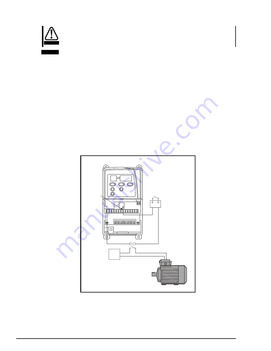
The following set-up should only be used in non-safety critical applications.
3.05
= 2.0
Zero speed threshold set to 2Hz (set to appropriate frequency as necessary)
8.21
=
9.01
Brake release output on terminal 8 - digital output
9.04
=
10.03
Logic function source 1 = zero speed
9.05
= 1
Logic function 1 source invert
9.06
=
12.01
Logic function source 2 = threshold level exceeded
9.09
= 0.2
Logic function delay of 0.2 seconds
12.03
=
4.01
Threshold source is motor current magnitude
12.04
= 10
Threshold level set to 10% (set to appropriate level as necessary)
12.05
= 10
Hysteresis level set to 10% (set to appropriate frequency as necessary)
Perform a Save routine:
xx.00
= 1000 and press red Stop / Reset button on the drive
From the above:
Brake release = Drive healthy & not zero speed (>2Hz) & 4.01 > threshold
The digital output signal MUST be fed through the drive healthy relay and should drive an external relay coil. The contacts of
this relay should feed the brake.
When the drive is healthy, the drives status relay will be closed. When the drives speed goes above 2Hz and the current
magnitude goes above the threshold, the digital output will go high. This will release the mechanical brake.
If the speed falls below 2Hz or the current falls below the threshold level, the digital output will go low engaging the brake. If
the drive trips while running, the status relay will open again causing the brake to be engaged.
This set-up is appropriate for forward or reverse applications but can cause an issue if you go from forward to reverse as the
brake can pulse on when the motor speed falls below the set zero speed threshold. If this is the case, the next example using
external circuitry must be implemented.
WARNING
NOTE
Power
supply
16
15
External
relay
N/O
Drive Healthy
relay
N/O
Digital
output
Motor (Brake)
U V W
Содержание COMMANDER SE
Страница 76: ...76 Commander SE Advanced User Guide Issue Number 4...
Страница 93: ...Commander SE Advanced User Guide 93 Issue Number 4...
Страница 98: ...98 Commander SE Advanced User Guide Issue Number 4...
Страница 142: ...142 Commander SE Advanced User Guide Issue Number 4 Figure 6 9 Input line reactor 4400 0241 All dimensions in mm...
Страница 144: ...144 Commander SE Advanced User Guide Issue Number 4 Figure 7 3 Commander SE Size 4 All dimensions in mm...


