6-2
BE1-BPR Communications
NOTE
For polled operation over the RS-485 interface, the hardware handshake (RTS/CTS),
software handshake (XON/XOFF), and echo options must be disabled on COM1 (i.e.
COM1=,H0,E0, XO).
COMMAND FORMAT
Each command consists of an ASCII string terminated by a carriage return, <CR>. A line feed <LF> is
optional. A semicolon may be used to separate multiple commands on a single line, however, the total line
length cannot exceed the size of the communication buffer (40 characters).
Command Format: [<ID>]<CMD1>[<;>CMD2<;>...<;>CMDn]<CR>[<LF>]
where
[ ]
=
Brackets identify optional parameters - brackets themselves are not part of
command.
< >
=
Separator used for clarity - not an actual part of the command
ID
=
Relay identifier used for RS-485 multi-drop (polled) communications.
CMDn
=
<Name>[#][<=> <Setting-1>...[<,><Setting-n>]]
Name
=
Command name (1 to 8 characters)
#
=
Numeric or phase identifier to limit command to a specific item
=
=
Used to indicate that the command is to change data/settings not to recall data
Setting-n
=
Command setting(s)
,
=
Comma used as setting separator
;
=
Semicolon used to separate multiple commands on the same line
CR
=
Carriage return used to end command and start execution.
LF
=
Line feed may be used for clarity. Ignored by relay.
Spaces
=
One or more spaces may be added between entries for clarity if desired
Commands received by the BE1-BPR relay consist of two general types: requests for information and
changes to operating parameters. Requests for information will always be accepted and executed, however
changes to operating parameters may be limited to access from personnel with the proper password.
Commands to change parameters are identified by an equals sign, '=', being included in the command. The
new operating parameters to the right of the equals sign are intended to replace the current operating
parameters related to the command.
Some commands may pertain to multiple items. In that case a numeric or phase identifier is used after the
command name to specify a single item. If the identifier is left off, the command applies to all possible items.
For example the IA command could be used to read the current on phase A or the I command without the
phase identifier would read the current on all inputs.
Multi-Drop (Polled) Command Operation
Each Relay can have a unique identification number programmed from 1-254. If the Relay internal ID is set
to 0 (zero), then polled operation is disabled and the ID prefix is not required as part of the command. If a
non-zero ID is programmed for the relay, the relay ID number must preface each command sent to the relay
through either of the rear communications ports. The command ID is never required from the front panel
communications port.
In polled mode, the relay waits until it is polled (i.e. - receives a command identified for it), then it responds.
Any data string that does not start with the proper ID will be ignored.
A unique ID is reserved to communicate with ALL relays operating in multi-drop mode and connected to the
same network. Any command prefaced by an ID of '!' will cause all Relays receiving the command to
execute the command but not to respond (BROADCAST OPERATION - NO RESPONSE). This type of
operation allows commands to be executed simultaneously by multiple relays. For example, 17TIME would
read the current time setting of Relay 17 and !TIME=12:05:37 would simultaneously set all relays on network
to the new time entered.
Содержание BE1-BPR
Страница 1: ...Publication 9 2720 00 990 Revision E 12 98 INSTRUCTION MANUAL for BE1 BPR BREAKER PROTECTION RELAY...
Страница 31: ...BE1 BPR Application 2 17...
Страница 41: ...BE1 BPR Human Machine Interface 3 3 Figure 3 3 BE1 BPR Relay Horizontal Mount Front And Rear Views...
Страница 42: ...3 4 BE1 BPR Human Machine Interface Figure 3 4 BE1 BPR Relay Vertical Mount Front View...
Страница 43: ...BE1 BPR Human Machine Interface 3 5 Figure 3 5 BE1 BPR Relay Vertical Mount Rear View...
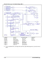
Страница 49: ...4 6 BE1 BPR Functional Description Figure 4 2 Enhanced BE1 BPR Menu Display Screens...
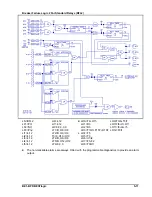
Страница 50: ...BE1 BPR Functional Description 4 7 Figure 4 3 Standard BE1 BPR Menu Display Screens...
Страница 94: ...5 4 BE1 BPR BESTlogic Figure 5 1 BESTlogic Function Blocks...
Страница 120: ...7 2 BE1 BPR Installation Figure 7 1 Overall Dimensions Figure 7 2 Cutout Dimensions Panel Mount...
Страница 121: ...BE1 BPR Installation 7 3 Figure 7 3 Overall Dimensions Vertical Mount...
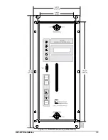
Страница 122: ...7 4 BE1 BPR Installation Figure 7 4 Overall Dimensions Side View Vertical Mount...
Страница 123: ...BE1 BPR Installation 7 5 Figure 7 5 Panel Drilling Diagram Vertical Mount...

