4-16
BE1-BPR Functional Description
7'
7'
7'
P
P
P
7'
7'
7'
V
V
V
7'
P
V
V
7'5 )
0
V
P
P
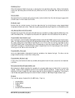
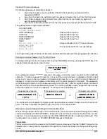
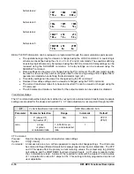
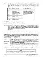
Sub-screen 2
Sub-screen 3
Sub-screen 4
Sub-screen 5
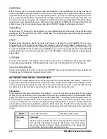
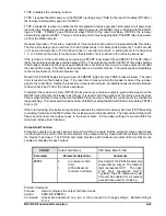
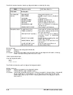
RELAY SETUP information can be reviewed or programmed through the communications ports as well.
The operational logic may be viewed or changed using the LOGIC command. A custom logic
scheme can be defined using the LN, LI, LF, LR, LT and LO commands. The equations defining
an existing logic scheme may be reviewed using the LINFO command. All relay settings can be
reviewed using the SHOWSET command. All relay settings can be reviewed using the
SHOWSET command.
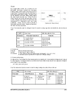
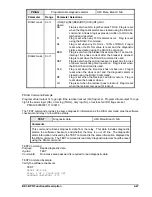
Pickup settings can be viewed or changed using the PU command. The PU command can also
be used to view or set the number of cycles used for the moving average filter if digital filter 2
operation is selected when defining the fault detector logic (LF).
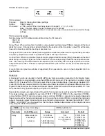
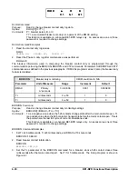
Time delay settings can be viewed or changed using the TD command.
Recloser timer delay settings can be viewed or changed using the TD79 command.
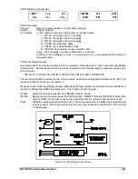
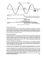
The current transformer ratios for phase and neutral CTs can be viewed or changed using the
CT command.
The 200 millisecond minimum hold time for the output contacts can be enabled or disabled.
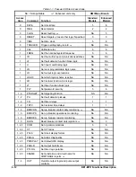
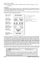
Transformer Ratios
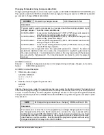
The CT command allows the relay to be matched to your system’s external current transformers. Separate
settings are provided for the phase and neutral CTs. CT ratio adjustment is not provided through the HMI.
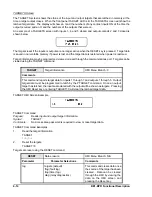
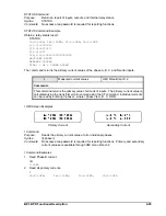
CT
Current transformer ratio information
HMI Menu Branch: N/A
Parameter
Parameter Selection
Range
Increment
Default
t
P (phase CT)
N (neutral CT)
N/A
N/A
CTP=1
CTN=1
ratio
pri:sec
or pri/sec
or calculated ratio
1 - 65535 for pri,
sec, and calculated
ratio
1
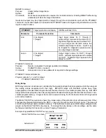
CT Command
Purpose:
Read or change the current transformer ratio settings
Syntax:
CT[t][=<ratio>]
Comments:
An access area one, two, or three password is required to change settings. The ct ratio can
be entered in three different formats but is always reported as the calculated ratio. The CTP
and CTN values affect the primary current metering values, the contact duty log (DLOG)
calculations, and the COMTRADE fault record current levels. A CTI value is reported when
the ct information is read. A value of 5 is reported for units with 5 ampere CTs and a value
of 1 is reported for units with 1 ampere CTs. This setting is factory programmed and is not
user adjustable.
Содержание BE1-BPR
Страница 1: ...Publication 9 2720 00 990 Revision E 12 98 INSTRUCTION MANUAL for BE1 BPR BREAKER PROTECTION RELAY...
Страница 31: ...BE1 BPR Application 2 17...
Страница 41: ...BE1 BPR Human Machine Interface 3 3 Figure 3 3 BE1 BPR Relay Horizontal Mount Front And Rear Views...
Страница 42: ...3 4 BE1 BPR Human Machine Interface Figure 3 4 BE1 BPR Relay Vertical Mount Front View...
Страница 43: ...BE1 BPR Human Machine Interface 3 5 Figure 3 5 BE1 BPR Relay Vertical Mount Rear View...
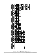
Страница 49: ...4 6 BE1 BPR Functional Description Figure 4 2 Enhanced BE1 BPR Menu Display Screens...
Страница 50: ...BE1 BPR Functional Description 4 7 Figure 4 3 Standard BE1 BPR Menu Display Screens...
Страница 94: ...5 4 BE1 BPR BESTlogic Figure 5 1 BESTlogic Function Blocks...
Страница 120: ...7 2 BE1 BPR Installation Figure 7 1 Overall Dimensions Figure 7 2 Cutout Dimensions Panel Mount...
Страница 121: ...BE1 BPR Installation 7 3 Figure 7 3 Overall Dimensions Vertical Mount...
Страница 122: ...7 4 BE1 BPR Installation Figure 7 4 Overall Dimensions Side View Vertical Mount...
Страница 123: ...BE1 BPR Installation 7 5 Figure 7 5 Panel Drilling Diagram Vertical Mount...


