4-14
BE1-BPR Functional Description
7$5*(76
, 2
7$5*(76
,
2
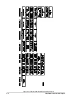
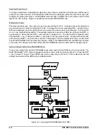
TARGETS Screen
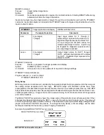
The TARGETS screen shows the status of the input and output targets that are latched in memory at the
time a target output closes. When the front panel TARGET LED is lit, the TARGETS screen will show the
latched target data. The display will show an I and the numbers of any contact inputs ON at the time the
output occurred and an O and the numbers of the outputs that were on.
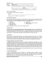
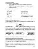
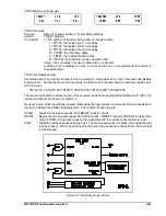
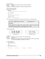
An example of a TARGETS screen with inputs 1, 4, and 5 closed and output contacts 2 and 3 closed is
shown below.
The targets reset if the inputs or outputs are no longer active when the RESET key is pressed. Target data
is saved in non-volatile memory if power is lost and the target data is restored when power is restored.
Target information may be programmed, viewed or reset through the communications port. Targets can be
viewed using the TARGET command.
TARGET
Target information
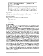
HMI Menu Branch: 0
Comments
This command reports target data for inputs 1 through 7 and outputs 1 through 5. Output
target data must be programmed to latch by the PTARGET command. Once an output
target has latched, the inputs associated with the output will be shown as targets. Pressing
the HMI Reset key or entering TARGET=0 will clear the latched target data.
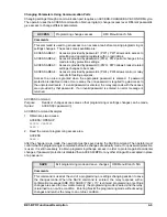
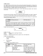
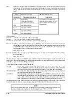
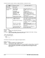
TARGET HMI Screen Example
TARGET Command
Purpose:
Reads input and output target information.
Syntax:
TARGET
Comments:
No access area password is required to view or reset target data.
TARGET Command Examples
1.
Read the target information.
TARGET
I-6,O-2
2.
Reset the targets.
TARGET=0
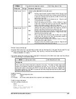
Targets are reset using the RESET command.
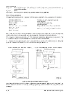
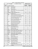
RESET
Data erasure
HMI Menu Branch: N/A
Parameter
Parameter Selections
Comments
log
targets (default)
flog (fault log)
tlog (timer log)
diag (relay diagnostics)
This command clears data once
the source of the target has been
cleared. Data can be cleared
through the HMI by viewing the
data on the HMI screen and
pressing the Reset key.
Содержание BE1-BPR
Страница 1: ...Publication 9 2720 00 990 Revision E 12 98 INSTRUCTION MANUAL for BE1 BPR BREAKER PROTECTION RELAY...
Страница 31: ...BE1 BPR Application 2 17...
Страница 41: ...BE1 BPR Human Machine Interface 3 3 Figure 3 3 BE1 BPR Relay Horizontal Mount Front And Rear Views...
Страница 42: ...3 4 BE1 BPR Human Machine Interface Figure 3 4 BE1 BPR Relay Vertical Mount Front View...
Страница 43: ...BE1 BPR Human Machine Interface 3 5 Figure 3 5 BE1 BPR Relay Vertical Mount Rear View...
Страница 49: ...4 6 BE1 BPR Functional Description Figure 4 2 Enhanced BE1 BPR Menu Display Screens...
Страница 50: ...BE1 BPR Functional Description 4 7 Figure 4 3 Standard BE1 BPR Menu Display Screens...
Страница 94: ...5 4 BE1 BPR BESTlogic Figure 5 1 BESTlogic Function Blocks...
Страница 120: ...7 2 BE1 BPR Installation Figure 7 1 Overall Dimensions Figure 7 2 Cutout Dimensions Panel Mount...
Страница 121: ...BE1 BPR Installation 7 3 Figure 7 3 Overall Dimensions Vertical Mount...
Страница 122: ...7 4 BE1 BPR Installation Figure 7 4 Overall Dimensions Side View Vertical Mount...
Страница 123: ...BE1 BPR Installation 7 5 Figure 7 5 Panel Drilling Diagram Vertical Mount...


