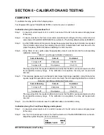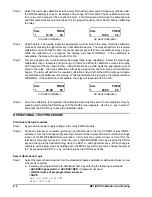
BE1-BPR Installation
7-7
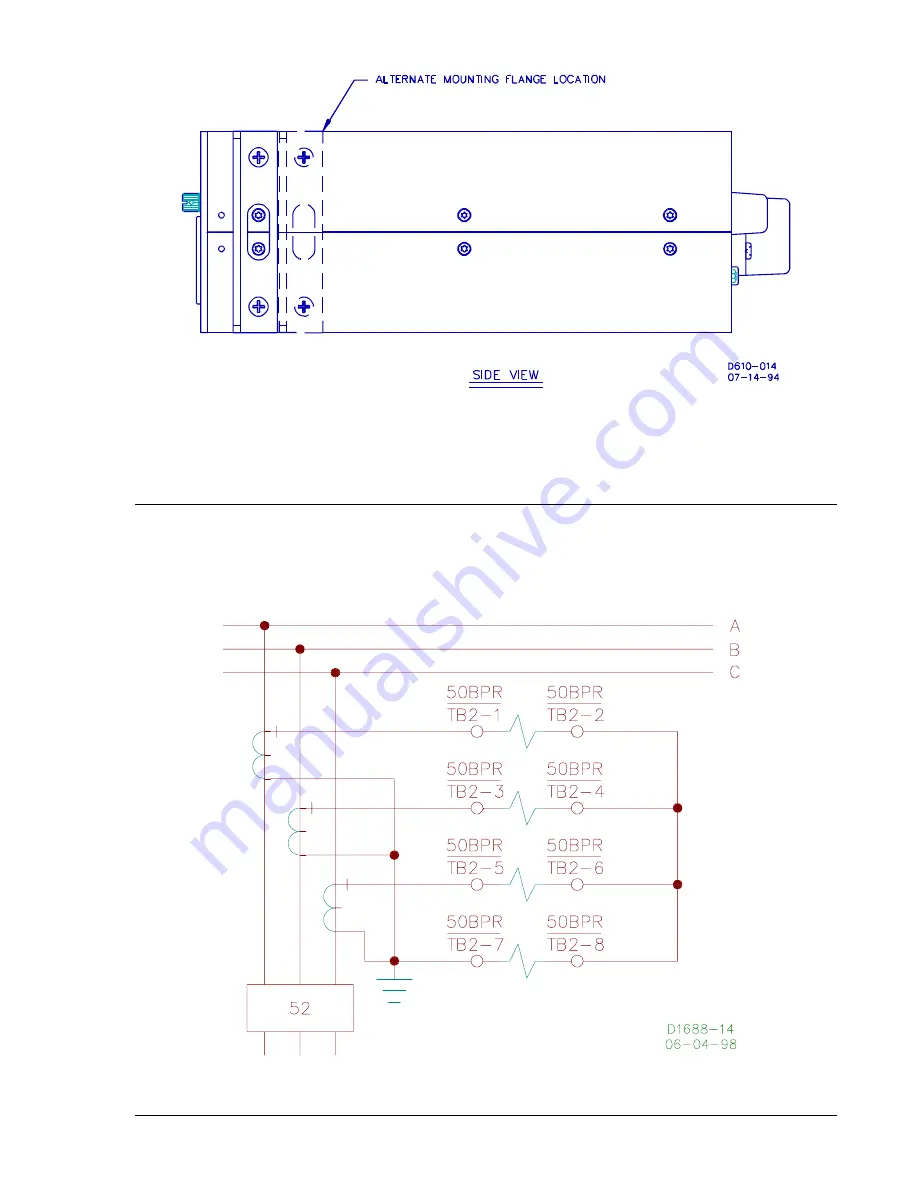
Figure 7-7. BE1-BPR Alternate Mounting Location (Vertical Mount Not Shown)
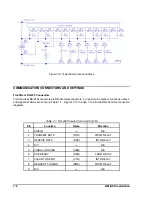
Figure 7-8. Typical External Sensing Connections
Westinghouse FT31 and FT32 cases
CONNECTIONS
Incorrect wiring may result in damage to the unit. Typical external sensing connections are shown in Figure
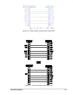
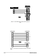
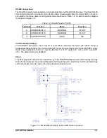
7-8. Connections for BE1-BPR relay terminals are identified in Figure 7-9. Terminals are suitable for use
with wire sizes 12 AWG or larger.
Содержание BE1-BPR
Страница 1: ...Publication 9 2720 00 990 Revision E 12 98 INSTRUCTION MANUAL for BE1 BPR BREAKER PROTECTION RELAY...
Страница 31: ...BE1 BPR Application 2 17...
Страница 41: ...BE1 BPR Human Machine Interface 3 3 Figure 3 3 BE1 BPR Relay Horizontal Mount Front And Rear Views...
Страница 42: ...3 4 BE1 BPR Human Machine Interface Figure 3 4 BE1 BPR Relay Vertical Mount Front View...
Страница 43: ...BE1 BPR Human Machine Interface 3 5 Figure 3 5 BE1 BPR Relay Vertical Mount Rear View...
Страница 49: ...4 6 BE1 BPR Functional Description Figure 4 2 Enhanced BE1 BPR Menu Display Screens...
Страница 50: ...BE1 BPR Functional Description 4 7 Figure 4 3 Standard BE1 BPR Menu Display Screens...
Страница 94: ...5 4 BE1 BPR BESTlogic Figure 5 1 BESTlogic Function Blocks...
Страница 120: ...7 2 BE1 BPR Installation Figure 7 1 Overall Dimensions Figure 7 2 Cutout Dimensions Panel Mount...
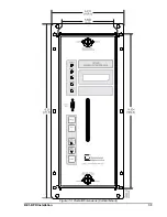
Страница 121: ...BE1 BPR Installation 7 3 Figure 7 3 Overall Dimensions Vertical Mount...
Страница 122: ...7 4 BE1 BPR Installation Figure 7 4 Overall Dimensions Side View Vertical Mount...
Страница 123: ...BE1 BPR Installation 7 5 Figure 7 5 Panel Drilling Diagram Vertical Mount...

