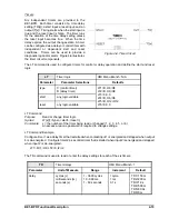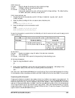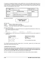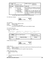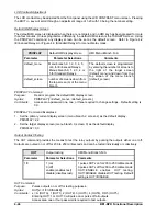
BE1-BPR Functional Description
4-31
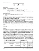
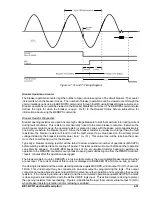
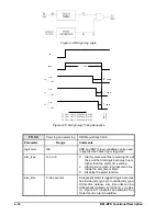
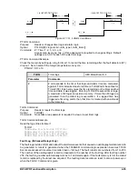
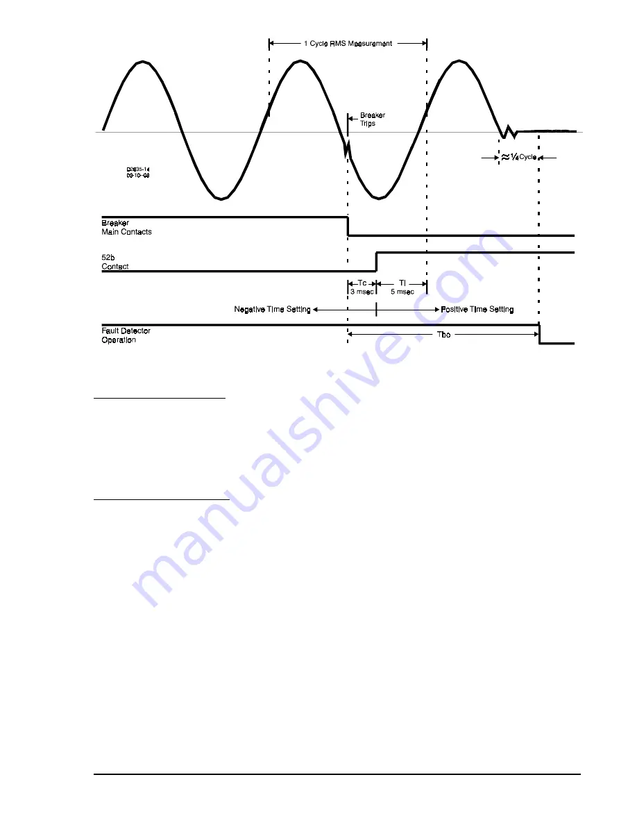
Figure 4-7. Tc and Ti Timing Diagram
Breaker Operations Counter
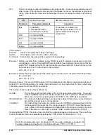
The breaker operations counter logs the number of open and close cycles of the circuit breaker. The counter
increments when the breaker closes. The number of breaker operations can be viewed or set through the
communications ports using the BKROPS command or through the HMI using Breaker Status sub-screen 3.
Breaker operations can also be viewed on the Breaker Status Menu Screen. The BKROPS command also
defines the logic for when the breaker is open. Refer to the
Breaker Status Screen sub-section for
information about using the BKROPS command.
Breaker Resistor Diagnostics
Breaker opening resistors are used on some high voltage breakers to limit the maximum interrupting current
during fault conditions. This resistor is mechanically linked to the main breaker contact so that when the
main breaker contact opens, the opening resistor is placed in series with the phase current approximately
one-half cycle before the breaker opens. Since the breaker resistor is usually much larger than the fault
resistance, the breaker resistor will tend to limit the fault current to a value based on the primary circuit
voltage divided by the breaker resistor value ( Ires = V
LN
/ R ). This value, Ires, will be less than the maxi-
mum short circuit rating (I
SC
) for the breaker.
Typically a breaker opening resistor will be rated to allow a maximum number of operations (MAXOPS)
before waiting a defined reset or cooling off period. This reset period must occur before another operation
can safely be allowed. The BE1-BPR keeps track of the accumulated resistor heating by adding one
operation to the RESOPS counter for every breaker opening and subtracting one from the RESOPS counter,
<reset> minutes after the operation was logged.
The breaker resistor counter, RESOPS, stores in volatile memory the accumulated breaker operations that
are not reset. The current status of this counter is displayed on BREAKER STATUS menu, sub_screen 2.
If reclosing is disabled and the accumulated operations equals MAXOPS, virtual output 13 (O13) becomes
TRUE. This virtual output may be connected to an actual output by programming the logic. This output
contact can provide a block reclose output (BRO) to prevent another operation and overheating the opening
resistors. If the reclosing function is enabled, and the accumulated operations equals MAXOPS, the block
reclose signal is internally ORed with the defined WAIT logic input. This action delays reclosing to protect
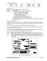
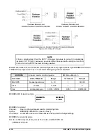
the opening resistors from overheating. Figure 4-8 illustrates the logic that controls virtual output 13 (O13)
when breaker resistor protection and/or reclosing is enabled.
Содержание BE1-BPR
Страница 1: ...Publication 9 2720 00 990 Revision E 12 98 INSTRUCTION MANUAL for BE1 BPR BREAKER PROTECTION RELAY...
Страница 31: ...BE1 BPR Application 2 17...
Страница 41: ...BE1 BPR Human Machine Interface 3 3 Figure 3 3 BE1 BPR Relay Horizontal Mount Front And Rear Views...
Страница 42: ...3 4 BE1 BPR Human Machine Interface Figure 3 4 BE1 BPR Relay Vertical Mount Front View...
Страница 43: ...BE1 BPR Human Machine Interface 3 5 Figure 3 5 BE1 BPR Relay Vertical Mount Rear View...
Страница 49: ...4 6 BE1 BPR Functional Description Figure 4 2 Enhanced BE1 BPR Menu Display Screens...
Страница 50: ...BE1 BPR Functional Description 4 7 Figure 4 3 Standard BE1 BPR Menu Display Screens...
Страница 94: ...5 4 BE1 BPR BESTlogic Figure 5 1 BESTlogic Function Blocks...
Страница 120: ...7 2 BE1 BPR Installation Figure 7 1 Overall Dimensions Figure 7 2 Cutout Dimensions Panel Mount...
Страница 121: ...BE1 BPR Installation 7 3 Figure 7 3 Overall Dimensions Vertical Mount...
Страница 122: ...7 4 BE1 BPR Installation Figure 7 4 Overall Dimensions Side View Vertical Mount...
Страница 123: ...BE1 BPR Installation 7 5 Figure 7 5 Panel Drilling Diagram Vertical Mount...


