BE1-BPR Functional Description
4-39
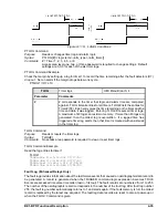
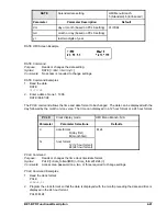
0$,17(1$1&(
7,0(
'$7(
$
&20)
&205
1
1
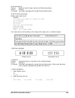
SNAME Command Example
For COMTRADE reporting, assign a relay identification number of 1 and a station name of Highland.
SNAME =1,HIGHLAND
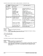
Downloading COMTRADE Files
COMTRADE oscillographic fault records consist of a configuration file and a data file. COMTRADE files can
be downloaded in binary or ASCII format using commercially available communication software such as
Windows
®
Terminal. The following paragraphs provide the procedure for downloading COMTRADE files.
1.
Determine which fault records are available for downloading by entering the FLOG command. The relay
will report which fault records are stored in memory.
2.
Select a fault record from the list of fault records available; e.g., 001.
3.
Begin transfer of the fault 001 configuration record by entering FLT001B.CFG for a binary download or
FLT001A.CFG for an ASCII download.
4.
The relay will respond with:
START XMODEM DOWNLOAD.
5.
Prior to downloading, the communication software will prompt you to enter a file name for the transferred
file. Typically, this would be the same as the data file. For example, if transferring Fault 001, you would
enter FLT1B or FLT1A. It is not necessary to include the zeros in the file name as long as the same file
naming convention is used for the CFG and DATA files.
6.
Once the file has been named, select start (if necessary) to begin transfer.
7.
Once the configuration file has transferred, begin transfer of the data record for fault 001 by entering
FLT001B.DAT or FLT001A.DAT. The relay will respond with:
START XMODEM DOWNLOAD.
8.
Prior to downloading, the communication software will prompt you to enter a file name for the transferred
file. Typically, this would be the same as the configuration file.
9.
Once the file has been named, select start (if necessary) to begin transfer.
Maintenance
Maintenance involves configuring and verifying essential features of the relay. These features may be pro-
grammed through the front panel controls or through the communications ports. A listing of these features
is provided below. The corresponding commands are listed in parenthesis. LCD contrast cannot be
adjusted through the communications ports. Output contact testing cannot be performed through the HMI.
&
Time and date settings (TIME, DATE, PCLK)
&
Communication port settings (COM)
&
Password settings (PW)
&
Fault detector calibration settings (CAL, FREQ)
&
HMI liquid crystal display (LCD) contrast
&
Default HMI display screen (PDISPLAY)
&
Output contact testing (OUT)
&
Software version reporting (VER)
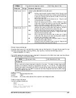
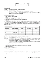
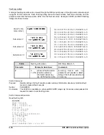
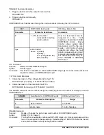
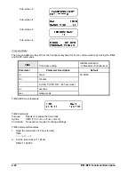
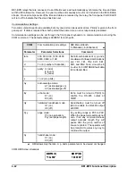
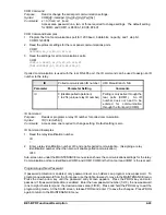
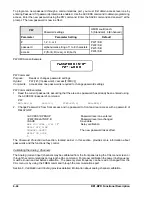
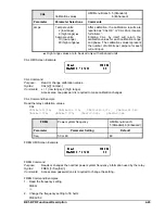
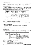
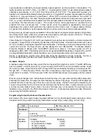
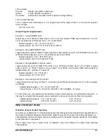
Examples of typical MAINTENANCE menu screens are shown below.
MAINTENANCE menu screen
Sub-screen 1
Sub-screen 2
Содержание BE1-BPR
Страница 1: ...Publication 9 2720 00 990 Revision E 12 98 INSTRUCTION MANUAL for BE1 BPR BREAKER PROTECTION RELAY...
Страница 31: ...BE1 BPR Application 2 17...
Страница 41: ...BE1 BPR Human Machine Interface 3 3 Figure 3 3 BE1 BPR Relay Horizontal Mount Front And Rear Views...
Страница 42: ...3 4 BE1 BPR Human Machine Interface Figure 3 4 BE1 BPR Relay Vertical Mount Front View...
Страница 43: ...BE1 BPR Human Machine Interface 3 5 Figure 3 5 BE1 BPR Relay Vertical Mount Rear View...
Страница 49: ...4 6 BE1 BPR Functional Description Figure 4 2 Enhanced BE1 BPR Menu Display Screens...
Страница 50: ...BE1 BPR Functional Description 4 7 Figure 4 3 Standard BE1 BPR Menu Display Screens...
Страница 94: ...5 4 BE1 BPR BESTlogic Figure 5 1 BESTlogic Function Blocks...
Страница 120: ...7 2 BE1 BPR Installation Figure 7 1 Overall Dimensions Figure 7 2 Cutout Dimensions Panel Mount...
Страница 121: ...BE1 BPR Installation 7 3 Figure 7 3 Overall Dimensions Vertical Mount...
Страница 122: ...7 4 BE1 BPR Installation Figure 7 4 Overall Dimensions Side View Vertical Mount...
Страница 123: ...BE1 BPR Installation 7 5 Figure 7 5 Panel Drilling Diagram Vertical Mount...

