1-4
BE1-BPR General Information
APPLICATION - ENHANCED MODELS
Enhanced BE1-BPR models have all of the features of standard models plus the additional features
described in the following paragraphs.
Breaker Contact Maintenance and Resistor Protection
Enhanced model BE1-BPR relays can perform two protection diagnostic functions other than the breaker
failure function. One, they can estimate breaker contact duty (wear) and signal when preventative
maintenance is needed. Two, they can estimate breaker opening resistor heating and provide a block
reclose signal to protect the breaker resistor when the resistor heating could exceed the maximum resistor
rating.
Fault Recording
Enhanced model BE1-BPR relays can also be configured to record and save digital fault data for all three
phases plus neutral (0 to 200 amperes) and the digital state of each input and output contact. Analog
waveforms are digitized by sampling the waveforms at a periodic rate and converting the measured signals
to digital values. When a fault occurs, the digital data is stored as a fault record. Multiple fault records can
be stored and recalled through the serial port by an operator. To display the fault waveform for analysis,
recalled data can be imported into a data base file and converted into a graph. Standard programs that read
and display ASCII data (in accordance with
IEEE Standard Common Format for Transient Data Exchange
(COMTRADE) for Power Systems) can also be used. BESTView application software provides a simple
terminal interface to communicate with the relay, retrieve and display COMTRADE oscillographic fault data,
and provide a remote front panel interface. This software is not required to communicate with the relay.
However, it combines the functions of a number of separate packages into one program that is optimized for
the BE1-BPR relay. To order this software free of charge, contact the Customer Service Department of the
Power Systems Group, Basler Electric, and request
BESTView Software Package, part number
9 2720 17 10.
MODEL NUMBERS
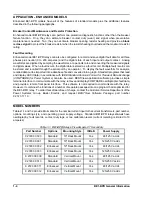
Tables 1-1 and 1-2 provide information for the nominal current input to the current transformers, part number,
options, mounting style, and operating power supply voltage. Standard BE1-BPR relays do not have
oscillography, fault records, contact duty logs, or two calibration levels (current metering is limited to 10
amperes).
Table 1-1. BE1-BPR Relays, Five-Ampere CT Secondary
Part Number
Options
Mounting Style
IRIG-B
Power Supply
9 2720 00 300
Standard
19" Rack Mount
Yes
48/125 V ac/dc
9 2720 00 301
Standard
19" Rack Mount
Yes
125/250 V ac/dc
9 2720 00 302
Enhanced
19" Rack Mount
Yes
48/125 V ac/dc
9 2720 00 303
Enhanced
19" Rack Mount
Yes
125/250 V ac/dc
9 2720 00 309
Standard
Vertical Mount
Yes
48/125 V ac/dc
9 2720 00 310
Standard
Vertical Mount
Yes
125/250 V ac/dc
9 2720 00 311
Enhanced
Vertical Mount
Yes
48/125 V ac/dc
9 2720 00 312
Enhanced
Vertical Mount
Yes
125/250 V ac/dc
Содержание BE1-BPR
Страница 1: ...Publication 9 2720 00 990 Revision E 12 98 INSTRUCTION MANUAL for BE1 BPR BREAKER PROTECTION RELAY...
Страница 31: ...BE1 BPR Application 2 17...
Страница 41: ...BE1 BPR Human Machine Interface 3 3 Figure 3 3 BE1 BPR Relay Horizontal Mount Front And Rear Views...
Страница 42: ...3 4 BE1 BPR Human Machine Interface Figure 3 4 BE1 BPR Relay Vertical Mount Front View...
Страница 43: ...BE1 BPR Human Machine Interface 3 5 Figure 3 5 BE1 BPR Relay Vertical Mount Rear View...
Страница 49: ...4 6 BE1 BPR Functional Description Figure 4 2 Enhanced BE1 BPR Menu Display Screens...
Страница 50: ...BE1 BPR Functional Description 4 7 Figure 4 3 Standard BE1 BPR Menu Display Screens...
Страница 94: ...5 4 BE1 BPR BESTlogic Figure 5 1 BESTlogic Function Blocks...
Страница 120: ...7 2 BE1 BPR Installation Figure 7 1 Overall Dimensions Figure 7 2 Cutout Dimensions Panel Mount...
Страница 121: ...BE1 BPR Installation 7 3 Figure 7 3 Overall Dimensions Vertical Mount...
Страница 122: ...7 4 BE1 BPR Installation Figure 7 4 Overall Dimensions Side View Vertical Mount...
Страница 123: ...BE1 BPR Installation 7 5 Figure 7 5 Panel Drilling Diagram Vertical Mount...

