BE1-BPR Functional Description
4-47
02'(/ %(%35
352*5$0 9(5 ;;;
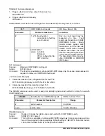
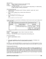
OUT Command Examples
1.
Enable the output test feature.
OUT=ENABLE
2.
Test output 1 by momentarily closing it.
OUT1=1
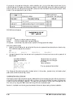
Firmware Version Display
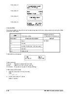
The firmware version may be viewed on the front panel HMI and through the communications ports. When
power is first applied to the relay, the firmware version is briefly displayed on the front panel LCD. The
firmware version can also be viewed at HMI Maintenance menu sub-screen 6. These screens are for
viewing only; the displayed firmware version cannot be altered.
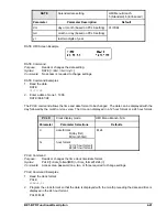
The VER command will return the software version number as well as the relay model, part, and serial
number.
VER
Relay version information
HMI Menu Branch:
5 (Standard), 6 (Enhanced)
Comments
This command returns the relay model number, the program version number, the relay part
number, and the relay serial number.
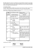
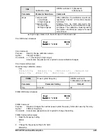
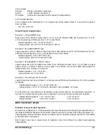
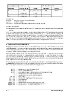
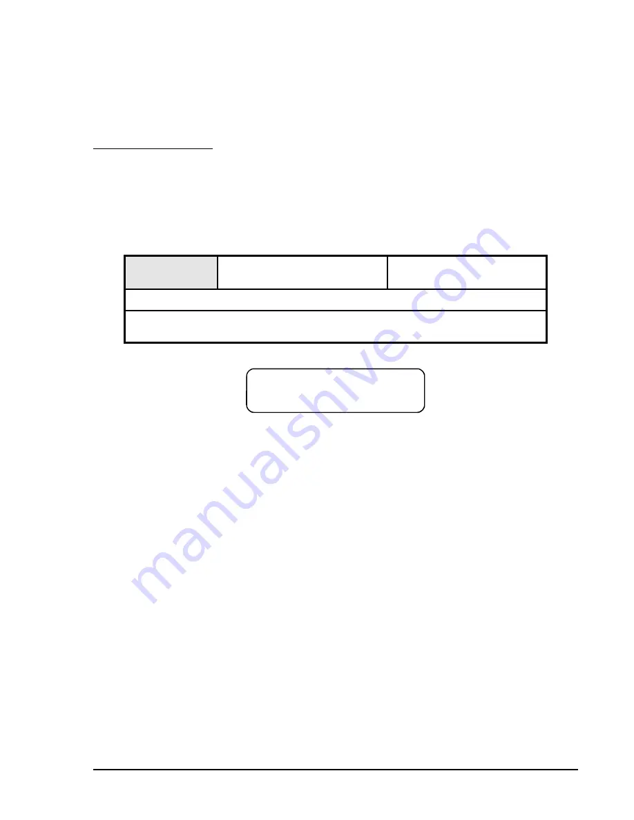
VER HMI Screen Example
VER Command
Purpose:
Returns information about relay hardware and software.
Syntax:
VER
Comments:
No access area password is required for reporting functions. Version information provided
through HMI is limited to the relay model number and software version number.
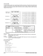
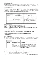
VER Command Example
Obtain the program version, part number, and serial number of the relay.
VER
Model
: BE1-BPR
Program
: VER 2.23E
PN
: 9 2720 00 101
SN
: UHG9827-001
Содержание BE1-BPR
Страница 1: ...Publication 9 2720 00 990 Revision E 12 98 INSTRUCTION MANUAL for BE1 BPR BREAKER PROTECTION RELAY...
Страница 31: ...BE1 BPR Application 2 17...
Страница 41: ...BE1 BPR Human Machine Interface 3 3 Figure 3 3 BE1 BPR Relay Horizontal Mount Front And Rear Views...
Страница 42: ...3 4 BE1 BPR Human Machine Interface Figure 3 4 BE1 BPR Relay Vertical Mount Front View...
Страница 43: ...BE1 BPR Human Machine Interface 3 5 Figure 3 5 BE1 BPR Relay Vertical Mount Rear View...
Страница 49: ...4 6 BE1 BPR Functional Description Figure 4 2 Enhanced BE1 BPR Menu Display Screens...
Страница 50: ...BE1 BPR Functional Description 4 7 Figure 4 3 Standard BE1 BPR Menu Display Screens...
Страница 94: ...5 4 BE1 BPR BESTlogic Figure 5 1 BESTlogic Function Blocks...
Страница 120: ...7 2 BE1 BPR Installation Figure 7 1 Overall Dimensions Figure 7 2 Cutout Dimensions Panel Mount...
Страница 121: ...BE1 BPR Installation 7 3 Figure 7 3 Overall Dimensions Vertical Mount...
Страница 122: ...7 4 BE1 BPR Installation Figure 7 4 Overall Dimensions Side View Vertical Mount...
Страница 123: ...BE1 BPR Installation 7 5 Figure 7 5 Panel Drilling Diagram Vertical Mount...

