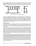
BE1-BPR Application
2-21
Breaker Failure Logic 2 For Enhanced Relays (BFL2E)
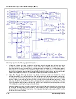
BFL2E logic provides the following application features:
1.
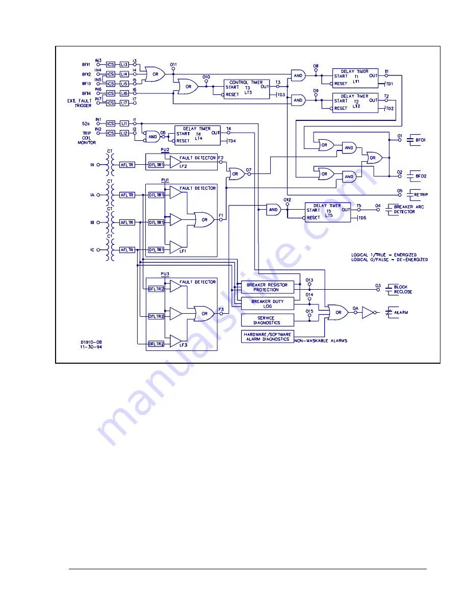
Three-Pole Tripping BF Logic (Output latch-in provided and Control timer limits operational window)
Three BFI inputs are available at IN3, IN4, and IN5 to start delay timer T1. If the BFI inputs are not reset
by the time Timer 1 times out and either the phase (F1) or neutral (F2) fault detector is still picked up,
then BFO1-2 will close (OUT1-2), tripping the backup breakers. Control timer (T3) is used to limit the
breaker failure window of opportunity. Refer to the breaker failure timing diagram in Section 1 for
information on setting the delay and control timers.
2.
Single-Pole Tripping BF Logic (Features: Output latch-in provided and Control timer limits operational
window). If single-pole tripping is used, a BFI input is available (IN6) to start delay timer T2. This input
is only supervised by the phase fault detector (F1). If the BFI input (IN6) is not reset by the time the
timer T2 times out and the phase fault detector (F1) is picked up, the BFO outputs (OUT1-2) closes,
tripping the backup breakers. Control timer, T3 is used to limit the breaker failure window of opportunity.
Refer to the breaker failure timing diagram in Section 1 for information on setting the delay and control
timers.
Neutral fault detector F2 is not used to supervise the single-pole BF logic because F2 is still picked up
by the phase imbalance after the fault clears. Three-phase BF logic is inhibited during this period
because there is no 3-phase BFI input active. For single-pole tripping, the phase pickup (PU1) must be
set above maximum load levels.
3.
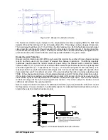
Trip Coil Status Monitor. Preprogrammed logic is provided using IN1 to provide breaker status and IN2
for trip coil continuity. Refer to
Application Data in this section for further details on the circuit operation.
Содержание BE1-BPR
Страница 1: ...Publication 9 2720 00 990 Revision E 12 98 INSTRUCTION MANUAL for BE1 BPR BREAKER PROTECTION RELAY...
Страница 31: ...BE1 BPR Application 2 17...
Страница 41: ...BE1 BPR Human Machine Interface 3 3 Figure 3 3 BE1 BPR Relay Horizontal Mount Front And Rear Views...
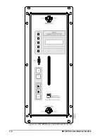
Страница 42: ...3 4 BE1 BPR Human Machine Interface Figure 3 4 BE1 BPR Relay Vertical Mount Front View...
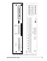
Страница 43: ...BE1 BPR Human Machine Interface 3 5 Figure 3 5 BE1 BPR Relay Vertical Mount Rear View...
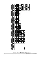
Страница 49: ...4 6 BE1 BPR Functional Description Figure 4 2 Enhanced BE1 BPR Menu Display Screens...
Страница 50: ...BE1 BPR Functional Description 4 7 Figure 4 3 Standard BE1 BPR Menu Display Screens...
Страница 94: ...5 4 BE1 BPR BESTlogic Figure 5 1 BESTlogic Function Blocks...
Страница 120: ...7 2 BE1 BPR Installation Figure 7 1 Overall Dimensions Figure 7 2 Cutout Dimensions Panel Mount...
Страница 121: ...BE1 BPR Installation 7 3 Figure 7 3 Overall Dimensions Vertical Mount...
Страница 122: ...7 4 BE1 BPR Installation Figure 7 4 Overall Dimensions Side View Vertical Mount...
Страница 123: ...BE1 BPR Installation 7 5 Figure 7 5 Panel Drilling Diagram Vertical Mount...


