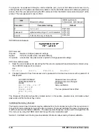
BE1-BPR Functional Description
4-43
COM Command
Purpose:
Read or change the serial port communication settings.
Syntax:
COM[x][=<ratedps>][,Ay][,Ey][,Hy][,Pyy][Xy]
Comments:
x = 0 (front) or 1 (rear)
Access area password one, two, or three required to change settings. The default setting
for COM0 and COM1 is 9600,A1,E0,H0,P24,X1.
COM Command Examples
1.
Program the front communications port for 1200 baud, 8 data bits, no parity, and 1 stop bit.
COM0=12008N1
2.
Read the protocol settings for the rear panel communications ports.
COM1
96008N1,A1,C0,E0,H1,P24,X1
3.
Read the settings for all communications ports.
COM
COM0=19.2K8N1,A1,C0,E0,H1,P24,X1
COM1=96008N1,A1,C0,E0,H1,P24,X1
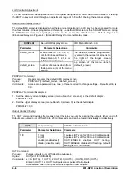
If polled communication is used with the rear RS-485 port, the ID command can be used to assign an ID
number to the relay.
ID
Polled communication ID number
HMI Menu Branch: N/A
Parameter
Parameter Setting
Comments
id
0 (disable polled operation)
1 to 254 (unique relay ID number)
Polling is only active through the
rear ports (COM1). An ID
number does not need to be
entered for communication
through the front port (COM0).
ID Command
Purpose:
Reads or programs a relay ID number for polled communication.
Syntax:
ID [=<id(0-254)>]
Comments:
Access area one required to change setting. Default setting is zero.
ID Command Examples
1.
Read the relay identification number.
ID
0
2.
Enter a relay identification number of 3 and enable polled communication. (Assigning a relay
identification number other than zero will enable polled communication.)
ID=3
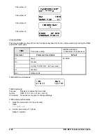
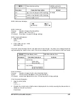
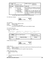
Sub-screen two under the MAINTENANCE menu screen shows the communications settings for the relay.
Communication ports are identified as COM0 and COM1; COM0 is the front port and COM1 is the rear port.
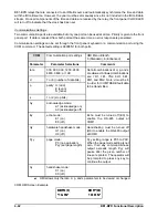
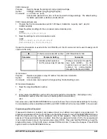
Programming A New Password
If password protection is enabled, only password level one holders can program a new password. To
program a new password from the front panel, use the right arrow key to move to the MAINTENANCE menu.
Press the down arrow key until the password entry screen appears. Press the PROG key and enter
password 1 if password protection is enabled. Enter the new password number (1/2/3), the new password
(one to eight characters) and the desired access area (F/R/B). Press and hold the PROG key to exit the
programming mode. At the SAVE screen, release PROG and enter Y to save the changes. Press PROG
again to return to the MAINTENANCE menu.
Содержание BE1-BPR
Страница 1: ...Publication 9 2720 00 990 Revision E 12 98 INSTRUCTION MANUAL for BE1 BPR BREAKER PROTECTION RELAY...
Страница 31: ...BE1 BPR Application 2 17...
Страница 41: ...BE1 BPR Human Machine Interface 3 3 Figure 3 3 BE1 BPR Relay Horizontal Mount Front And Rear Views...
Страница 42: ...3 4 BE1 BPR Human Machine Interface Figure 3 4 BE1 BPR Relay Vertical Mount Front View...
Страница 43: ...BE1 BPR Human Machine Interface 3 5 Figure 3 5 BE1 BPR Relay Vertical Mount Rear View...
Страница 49: ...4 6 BE1 BPR Functional Description Figure 4 2 Enhanced BE1 BPR Menu Display Screens...
Страница 50: ...BE1 BPR Functional Description 4 7 Figure 4 3 Standard BE1 BPR Menu Display Screens...
Страница 94: ...5 4 BE1 BPR BESTlogic Figure 5 1 BESTlogic Function Blocks...
Страница 120: ...7 2 BE1 BPR Installation Figure 7 1 Overall Dimensions Figure 7 2 Cutout Dimensions Panel Mount...
Страница 121: ...BE1 BPR Installation 7 3 Figure 7 3 Overall Dimensions Vertical Mount...
Страница 122: ...7 4 BE1 BPR Installation Figure 7 4 Overall Dimensions Side View Vertical Mount...
Страница 123: ...BE1 BPR Installation 7 5 Figure 7 5 Panel Drilling Diagram Vertical Mount...


