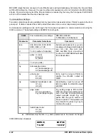
4-30
BE1-BPR Functional Description
'/2*
$
%
&
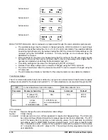
DLOG Command
Purpose:
Read or change breaker contact duty log data.
Syntax:
DLOG[P][=<YY>]
Comments:
P = breaker pole A, B, or C
YY = accumulated breaker pole duty as a percent of the DMAX setting
This function is available on enhanced BE1-BPR relays only. An access area one or three
password is required to change settings.
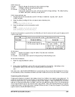
DLOG Command Examples
1.
Read the contact duty log values.
DLOG
DLOGA= 92; DLOGB= 22; DLOGC= 27
2.
Reset the Phase A duty log after maintenance was performed.
DLOGA=0
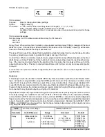
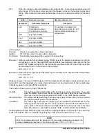
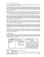
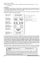
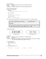
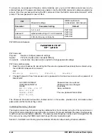
The breaker information used in computing the breaker contact duty is programmed through the
communication port using the BKRCON, BKROPS, and CTP commands. Parameters for BKROPS and CTP
commands are as defined in the previous paragraphs. If DMAX is programmed as 0 (zero) the breaker duty
feature is disabled.
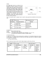
BKRCON
Breaker duty monitoring
HMI Menu Branch: N/A
Parameter
Unit of Measure
Range
Increment
Default
DMAX
Primary
A
2
seconds
0 - 6.8E38
0.001
0.000E00
Tc
milliseconds
0 - ±50
1
0
Ti
milliseconds
0 - ±50
1
0
BKRCON Command
Purpose:
Read or change breaker contact duty monitoring settings.
Syntax:
BKRCON[=<DMAX>,<Tc>,<Ti>]
Comments:
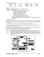
Tc is a negative value when the 52b contacts change state after the main contacts open. Tc
is a positive value when the 52b contacts change state before the main contacts open. Ti sets
the point where the last full cycle of current calculations ends.
This function is available on enhanced BE1-BPR relays only. An access area one or three
password is required to change settings.
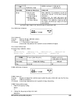
BKRCON Command Examples
1.
Set Tc at 6 milliseconds, Ti at 8 milliseconds, and DMAX at 10 kA-seconds
BKRCON=1.0E4,6,8
2.
Read breaker contact information.
BKRCON
BKRCON=1.0E4
,
8,8
3.
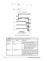
Set the Tc parameter of the BKRCON command for a breaker whose 52b contact closes three
milliseconds after the main contacts part. Set Ti for 5 milliseconds. The timing diagram is shown in
Figure 4-7.
Содержание BE1-BPR
Страница 1: ...Publication 9 2720 00 990 Revision E 12 98 INSTRUCTION MANUAL for BE1 BPR BREAKER PROTECTION RELAY...
Страница 31: ...BE1 BPR Application 2 17...
Страница 41: ...BE1 BPR Human Machine Interface 3 3 Figure 3 3 BE1 BPR Relay Horizontal Mount Front And Rear Views...
Страница 42: ...3 4 BE1 BPR Human Machine Interface Figure 3 4 BE1 BPR Relay Vertical Mount Front View...
Страница 43: ...BE1 BPR Human Machine Interface 3 5 Figure 3 5 BE1 BPR Relay Vertical Mount Rear View...
Страница 49: ...4 6 BE1 BPR Functional Description Figure 4 2 Enhanced BE1 BPR Menu Display Screens...
Страница 50: ...BE1 BPR Functional Description 4 7 Figure 4 3 Standard BE1 BPR Menu Display Screens...
Страница 94: ...5 4 BE1 BPR BESTlogic Figure 5 1 BESTlogic Function Blocks...
Страница 120: ...7 2 BE1 BPR Installation Figure 7 1 Overall Dimensions Figure 7 2 Cutout Dimensions Panel Mount...
Страница 121: ...BE1 BPR Installation 7 3 Figure 7 3 Overall Dimensions Vertical Mount...
Страница 122: ...7 4 BE1 BPR Installation Figure 7 4 Overall Dimensions Side View Vertical Mount...
Страница 123: ...BE1 BPR Installation 7 5 Figure 7 5 Panel Drilling Diagram Vertical Mount...

