BE1-BPR Functional Description
4-19
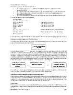
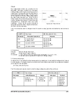
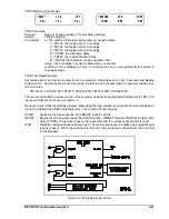
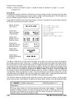
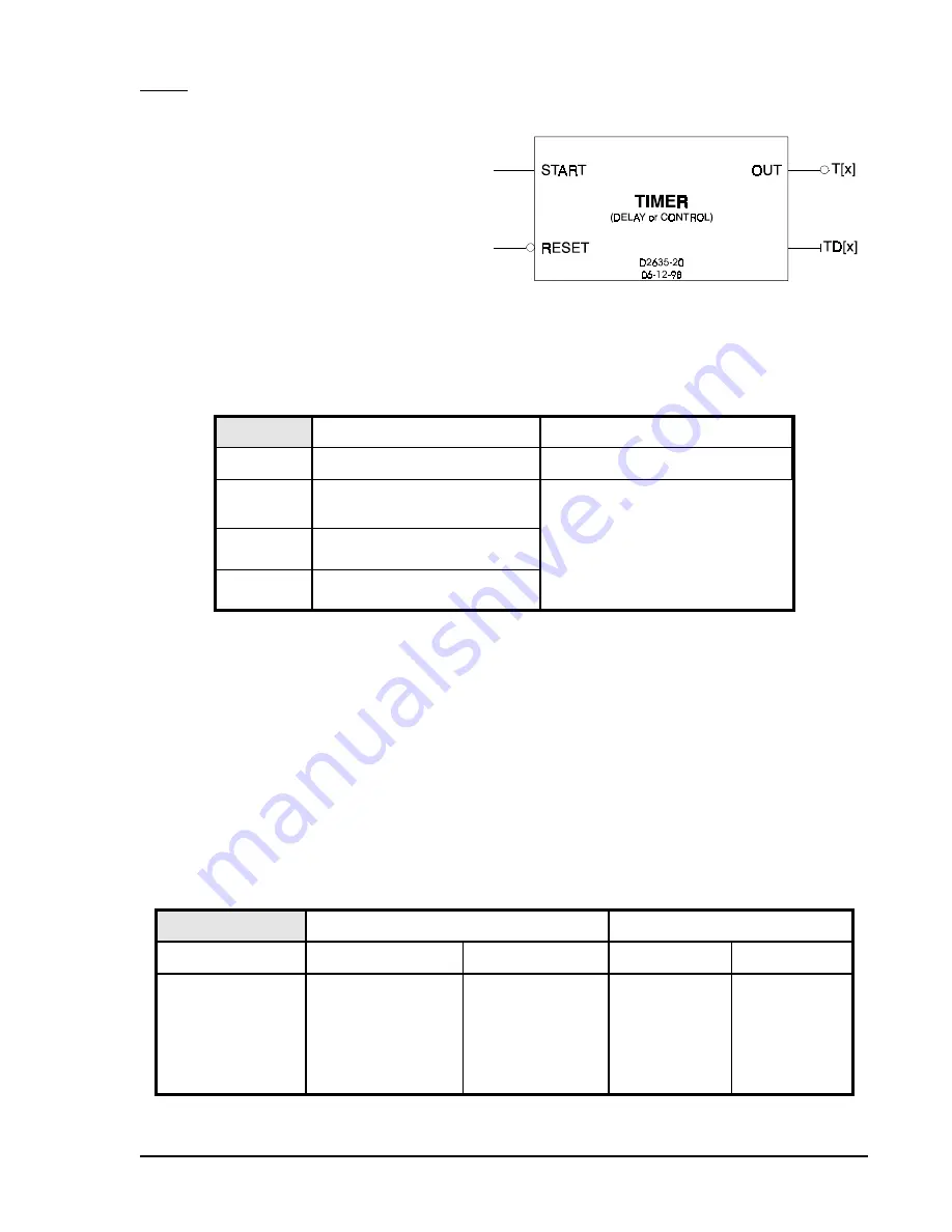
Figure 4-6. Timer Circuit
Timers
Six independent timers are provided in the
BE1-BPR. Each timer consists of a time delay
setting (TD[x]), a start input, a reset input, and an
output (T[x]). Timing starts when the start input is
true and the reset input is false. The timer runs
for the duration of the time delay setting unless
the reset input becomes true. When the time
delay expires, the output changes state. A timer
can be configured as a delay or control timer with
independent or dependent start and reset
conditions. Timers can be used to provide a
diagnostic log and/or alarm. Figure 4-6 illustrates
the timer circuit components.
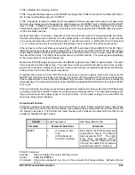
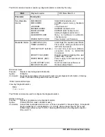
The LT command is used to configure timers for control or delay operation and define the start and reset
logic.
LT
Timer logic
HMI Menu Branch: N/A
Parameter
Parameter Selections
Defaults
type
C (control timer)
D (delay timer)
LT1=D,O8,/O8
LT2=D,O9,/O9
LT3=0,0,0
LT4=D,O6,/O6
LT5=D,O12,/O12
LT6=0,0,0
start
any logic variable
reset
any logic variable
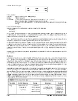
LT Command
Purpose:
Read or change timer logic
Syntax:
LT[x][=<type>,<start>,<reset>]
Comments:
x = the number of the timer being read or changed (1, 2, 3, 4, 5, or 6)
An access area one password is required to change settings.
LT Command Example
Configure timer 1 as a delay timer that is started when contact input 1 is energized and stopped when output
6 is de-energized. Configure timer 2 as a control timer that is started when input 2 is energized and stopped
when input 2 is de-energized.
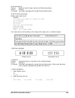
LT1=D,I1,/O6; LT2=C,I2,/I2
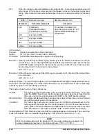
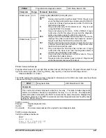
The TD command is used to read or enter the delay settings for each of the six timers.
TD
Timer delays
HMI Menu Branch: 1
Parameter
Unit of Measure
Range
Increment
Default
delay
cycles (c)
milliseconds (m)
seconds (s)
1 - 3600 cycles
10 - 999 ms
1 - 60 seconds
1 cycle
1 ms
0.1 s
TD1=150m
TD2=200m
TD3=1.0s
TD4=500m
TD5=30.0s
TD6=0m
Содержание BE1-BPR
Страница 1: ...Publication 9 2720 00 990 Revision E 12 98 INSTRUCTION MANUAL for BE1 BPR BREAKER PROTECTION RELAY...
Страница 31: ...BE1 BPR Application 2 17...
Страница 41: ...BE1 BPR Human Machine Interface 3 3 Figure 3 3 BE1 BPR Relay Horizontal Mount Front And Rear Views...
Страница 42: ...3 4 BE1 BPR Human Machine Interface Figure 3 4 BE1 BPR Relay Vertical Mount Front View...
Страница 43: ...BE1 BPR Human Machine Interface 3 5 Figure 3 5 BE1 BPR Relay Vertical Mount Rear View...
Страница 49: ...4 6 BE1 BPR Functional Description Figure 4 2 Enhanced BE1 BPR Menu Display Screens...
Страница 50: ...BE1 BPR Functional Description 4 7 Figure 4 3 Standard BE1 BPR Menu Display Screens...
Страница 94: ...5 4 BE1 BPR BESTlogic Figure 5 1 BESTlogic Function Blocks...
Страница 120: ...7 2 BE1 BPR Installation Figure 7 1 Overall Dimensions Figure 7 2 Cutout Dimensions Panel Mount...
Страница 121: ...BE1 BPR Installation 7 3 Figure 7 3 Overall Dimensions Vertical Mount...
Страница 122: ...7 4 BE1 BPR Installation Figure 7 4 Overall Dimensions Side View Vertical Mount...
Страница 123: ...BE1 BPR Installation 7 5 Figure 7 5 Panel Drilling Diagram Vertical Mount...

