BE1-BPR Communications
6-1
SECTION 6 • COMMUNICATIONS
GENERAL
Communications allow the operator to retrieve information about the relay or power system from a remote
location and to request special reports. It also allows the operator to select a specific system protection
scheme or to completely reprogram the relay for a new scheme. A communication port on the front of the
relay provides a temporary, local interface for all communication functions. Rear ports provide a permanent
interface for communications to other areas.
Interface
Communication capability is provided on the relay front and rear panels. The front panel interface mates with
standard RS-232 (DB-9, male) connectors. The rear panel interface uses standard RS-232 (DB-9) and RS-
485 (Terminal Block) connections. The relay communications protocol is compatible with readily available
modem/terminal software. The RS-232 communication ports use the DCE (data circuit-terminating
equipment) type interface and support full duplex operation. The RS-485 communication port supports half
duplex multi-drop operation. Only one port, front or rear, may be used at a time. The rear port is the default
port, but operation will automatically switch to the front port if a hardware handshake line (CTS) is asserted.
If the rear communication port is active when the front port is enabled, the current command is completed
and the handshake (CTS) line at the rear port will be de-asserted. As soon as communication ceases, the
relay will switch to the front port and assert the front panel handshake line (RTS). Only one rear port
interface (RS-232 or RS-485) may be used at a time.
Applications
The front panel communication port, COM0, is intended for short term local communication. Hardware
security is provided by a wire seal on the front panel which limits unauthorized access. Password protection
provides additional security if required.
Rear panel communications ports, COM1A and COM1B, are intended for continuous operation. They
support either RS-232 (COM1A) or RS-485 (COM1B) communications. The RS-485 port (COM1B) and
RS-232 port (COM1A) use the same address so that they can be multi-dropped (polled mode). Although not
intended for multi-dropping, COM1A can be used this way with a RS-232 splitter. COM1A and COM1B ports
are located on physically separate connectors but are internally connected to the same data stream. The
rear panel communication ports have no hardware security other than the mounting panel enclosure.
Password protection provides additional security if required.
Front and rear panel communication ports may be used to interface terminals, computers, serial printers,
modems, and intermediate communication/control interfaces such as RS-232 serial multiplexors. Relay
communications protocols support ASCII and binary data transmissions. ASCII data is used to send and
receive human readable data and commands. Binary data is used for transmission of raw oscillographic fault
data.
BESTview for Windows
TM
BESTview for Windows
TM
is a software application program that enables communication between personal
computers and BE1-BPR relays. Through BESTview, you can retrieve and display COMTRADE
oscillographic fault data, access the front panel from a remote location to change settings, retrieve a
computer file of the relay settings, or send a computer file to the relay to perform all relay settings. For a free
copy of BESTview for Windows
TM
, contact the Customer Service Department of the Basler Electric Power
Systems Group at 618-654-2341.
Содержание BE1-BPR
Страница 1: ...Publication 9 2720 00 990 Revision E 12 98 INSTRUCTION MANUAL for BE1 BPR BREAKER PROTECTION RELAY...
Страница 31: ...BE1 BPR Application 2 17...
Страница 41: ...BE1 BPR Human Machine Interface 3 3 Figure 3 3 BE1 BPR Relay Horizontal Mount Front And Rear Views...
Страница 42: ...3 4 BE1 BPR Human Machine Interface Figure 3 4 BE1 BPR Relay Vertical Mount Front View...
Страница 43: ...BE1 BPR Human Machine Interface 3 5 Figure 3 5 BE1 BPR Relay Vertical Mount Rear View...
Страница 49: ...4 6 BE1 BPR Functional Description Figure 4 2 Enhanced BE1 BPR Menu Display Screens...
Страница 50: ...BE1 BPR Functional Description 4 7 Figure 4 3 Standard BE1 BPR Menu Display Screens...
Страница 94: ...5 4 BE1 BPR BESTlogic Figure 5 1 BESTlogic Function Blocks...
Страница 120: ...7 2 BE1 BPR Installation Figure 7 1 Overall Dimensions Figure 7 2 Cutout Dimensions Panel Mount...
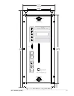
Страница 121: ...BE1 BPR Installation 7 3 Figure 7 3 Overall Dimensions Vertical Mount...
Страница 122: ...7 4 BE1 BPR Installation Figure 7 4 Overall Dimensions Side View Vertical Mount...
Страница 123: ...BE1 BPR Installation 7 5 Figure 7 5 Panel Drilling Diagram Vertical Mount...

