BE1-BPR General Information
1-3
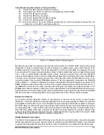
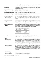
Figure 1-1. Breaker Failure Timing Diagram
Failed Breaker Operation Required Timing Information
(5)
Time for the BFI overcurrent detector to pickup.
(6)
Time required for the BFI contact to be recognized by the BE1-BPR.
(7)
Time for the BF logic to operate.
(8)
Time for the BFO relay to operate.
(9)
Time for the external lockout relay to pickup.
(10) Time for the backup breakers to operate.
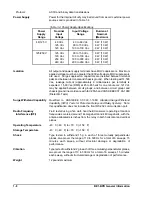
(11) Delay timer setting = the sum of (breaker operate time (2) + BF current detector dropout time (3)
+ margin (4) ) minus BFI contact pickup time (6).
Because timing is such an important part of breaker failure protection, the BE1-BPR relay provides timing
diagnostics to assist in determining if the timer settings are optimal and to allow other aspects of the
protection system to be checked. This timing diagnostic is a Timer Log or TLOG. An example of its use is
to create a log of the margin remaining between when a fault is cleared and when a breaker failure would
occur. After a normal breaker operation clears a fault, the time remaining from when the BE1-BPR
overcurrent fault detector drops out and the breaker failure delay timer would have timed out is the MARGIN.
This time can be recorded by saving the time left on the delay timer when the fault detector drops out by
using the program timer log alarm (PTLOG) command. The time logged will correspond to the MARGIN
value in Figure 1-1. If there is a discrepancy between the calculated and actual margin value stored in the
TLOG, corrective action can be taken to correct the protection timing before a serious problem occurs. If
the MARGIN is too small or too large, the delay timer setting can be adjusted for optimal operation. The
PTLOG command also allows an alarm time to be programmed so that if the MARGIN drops below a pre-
determined value, the Alarm output (ALM) can be automatically closed to signal the operator that immediate
attention is required. Timing diagnostics can be programmed for each of the six timers available.
Breaker Arc Detector
An important breaker diagnostic feature is the detection of low level arcing across an open breaker
(flashover). Flashover might occur because lightning struck and a surge suppressor failed or air pressure
in an airblast circuit breaker is lost. If left undetected, severe damage to the breaker contacts could result.
BE1-BPR relays can detect this type of fault using an extra low level phase overcurrent pickup and a long
moving average filter. These features have been provided as standard features in the BE1-BPR relays.
Used with the programmable logic, a breaker arc detector can be programmed to provide a breaker close
output to close the breaker and extinguish the arc. Additional interlocks may be added to the logic to inhibit
the breaker close signal if the breaker is isolating a faulted line.
IRIG-B Standard Time Format
The IRIG-B function allows the BE1-BPR relay to synchronize the on-board real time clock with a standard
IRIG-B demodulated time signal. Synchronization is automatic and the BE1-BPR initiates synchronization
at regular intervals (approximately 20 seconds) in order to maintain the one millisecond overall accuracy.
Содержание BE1-BPR
Страница 1: ...Publication 9 2720 00 990 Revision E 12 98 INSTRUCTION MANUAL for BE1 BPR BREAKER PROTECTION RELAY...
Страница 31: ...BE1 BPR Application 2 17...
Страница 41: ...BE1 BPR Human Machine Interface 3 3 Figure 3 3 BE1 BPR Relay Horizontal Mount Front And Rear Views...
Страница 42: ...3 4 BE1 BPR Human Machine Interface Figure 3 4 BE1 BPR Relay Vertical Mount Front View...
Страница 43: ...BE1 BPR Human Machine Interface 3 5 Figure 3 5 BE1 BPR Relay Vertical Mount Rear View...
Страница 49: ...4 6 BE1 BPR Functional Description Figure 4 2 Enhanced BE1 BPR Menu Display Screens...
Страница 50: ...BE1 BPR Functional Description 4 7 Figure 4 3 Standard BE1 BPR Menu Display Screens...
Страница 94: ...5 4 BE1 BPR BESTlogic Figure 5 1 BESTlogic Function Blocks...
Страница 120: ...7 2 BE1 BPR Installation Figure 7 1 Overall Dimensions Figure 7 2 Cutout Dimensions Panel Mount...
Страница 121: ...BE1 BPR Installation 7 3 Figure 7 3 Overall Dimensions Vertical Mount...
Страница 122: ...7 4 BE1 BPR Installation Figure 7 4 Overall Dimensions Side View Vertical Mount...
Страница 123: ...BE1 BPR Installation 7 5 Figure 7 5 Panel Drilling Diagram Vertical Mount...

