3-2
BE1-BPR Human-Machine Interface
NOTE
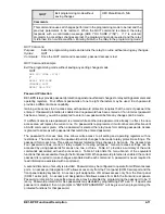
PROGRAM mode must be enabled in order for the EDIT +/- key to
operate.
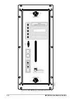
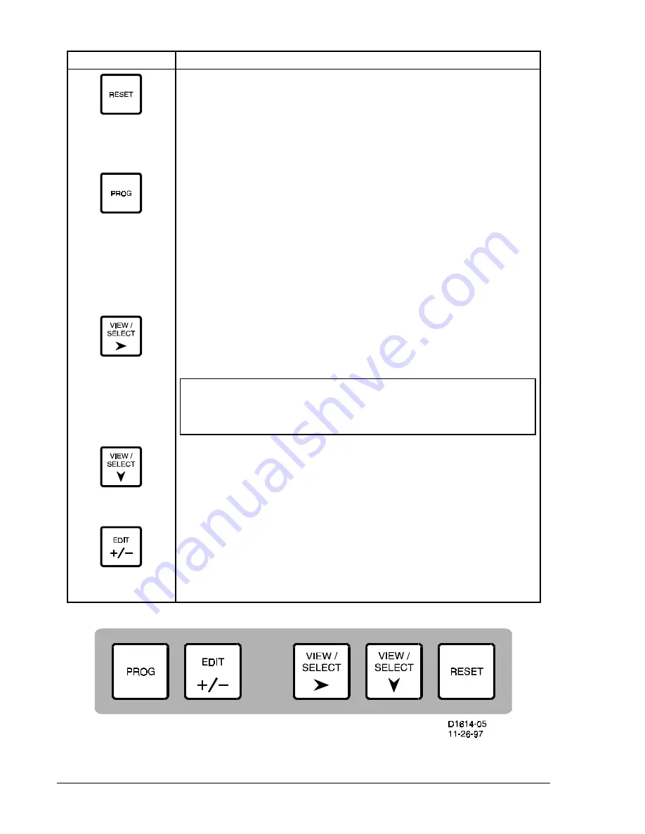
Figure 3-2. BE1-BPR Controls (Switches)
(Vertical Mount Not Shown)
Table 3-2. Front Panel Switch Operation (Refer to Figure 3-2)
Switch Function
Returns the cursor to the top of the current menu. If the current screen is the
target screen or a diagnostic screen, this switch resets (clears) the target or
diagnostic information.
When held for 2 seconds in the PROGRAM mode, exits the PROGRAM mode
without saving changes.
When first pressed, enables the PROGRAM mode which allows settings
changes. A password may have to be entered before PROGRAM mode is
entered.
If PROG key and then EDIT +/- key are pressed, the direction of the change
is reversed until a new key other than EDIT +/- is pressed.
When held for 2 seconds in PROGRAM mode, brings up the SAVE screen,
which allows the operator to save changes made to non-volatile memory or exit
without saving changes.
Selects the next menu to view. After the last menu, the display returns to the
first menu.
In PROGRAM mode, selects the next number or string to change.
Selects different menu screens to view. After the last menu screen, the
display returns to the top of the menu.
In PROGRAM mode, selects a different screen for programming changes
(settings).
Changes the ITEM selected, usually a character or a string, to the next
possible value.
If PROG key and then EDIT +/- key are pressed, the direction of the change
is reversed until a new key other than +/- is pressed.
Содержание BE1-BPR
Страница 1: ...Publication 9 2720 00 990 Revision E 12 98 INSTRUCTION MANUAL for BE1 BPR BREAKER PROTECTION RELAY...
Страница 31: ...BE1 BPR Application 2 17...
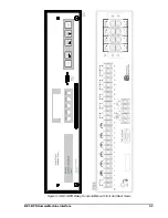
Страница 41: ...BE1 BPR Human Machine Interface 3 3 Figure 3 3 BE1 BPR Relay Horizontal Mount Front And Rear Views...
Страница 42: ...3 4 BE1 BPR Human Machine Interface Figure 3 4 BE1 BPR Relay Vertical Mount Front View...
Страница 43: ...BE1 BPR Human Machine Interface 3 5 Figure 3 5 BE1 BPR Relay Vertical Mount Rear View...
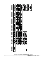
Страница 49: ...4 6 BE1 BPR Functional Description Figure 4 2 Enhanced BE1 BPR Menu Display Screens...
Страница 50: ...BE1 BPR Functional Description 4 7 Figure 4 3 Standard BE1 BPR Menu Display Screens...
Страница 94: ...5 4 BE1 BPR BESTlogic Figure 5 1 BESTlogic Function Blocks...
Страница 120: ...7 2 BE1 BPR Installation Figure 7 1 Overall Dimensions Figure 7 2 Cutout Dimensions Panel Mount...
Страница 121: ...BE1 BPR Installation 7 3 Figure 7 3 Overall Dimensions Vertical Mount...
Страница 122: ...7 4 BE1 BPR Installation Figure 7 4 Overall Dimensions Side View Vertical Mount...
Страница 123: ...BE1 BPR Installation 7 5 Figure 7 5 Panel Drilling Diagram Vertical Mount...


