BE1-BPR Functional Description
4-15
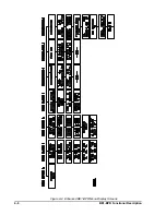
5(/$< 6(783
/2*,& %)/
38
38
38
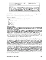
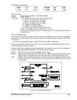
RESET Command
Purpose:
Clears latched target data.
Syntax:
RESET
Comments:
No access area password is required to clear latched data. Entering RESET without a log
parameter will clear the target information.
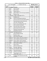
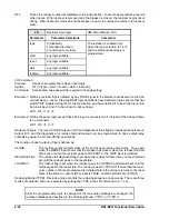
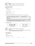
Inputs and outputs may be programmed as targets through the communication port with the PTARGET
command. Inputs and outputs not included in the PTARGET mask will not give a target indication when the
input or output is active.
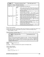
PTARGET
Target operation and display
HMI Menu Branch: N/A
Parameter
Parameter Selection
Comments
iiiiiii
0 (no target)
1 (target)
Input target status for I1 through I7.
Leftmost digit represents the status for I1.
Rightmost digit represents the status for I7.
An input target will not latch unless the
related output target is active. Inputs may
be targeted for diagnostic purposes when
an output target is latched.
ooooo
0 (no target)
1 (target)
Output target status for OUT1 through
OUT5. Leftmost digit represents the status
for OUT1. Rightmost digit represents the
status for OUT5.
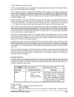
PTARGET Command
Purpose:
Reads or programs the target operation and display.
Syntax:
PARGET[=<iiiiiii>,<ooooo>]
Comments:
Access area one or two password is required to change settings.
PTARGET Command Example
Program outputs 1, 2, and 3 to target.
PTARGET=0000000,11100
Relay Setup
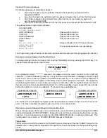
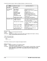
BPR relay protective functions are controlled by the operational logic that is programmed into the relay and
the setting values associated with that logic. BE1-BPR relays with standard options have three
preprogrammed breaker failure logic schemes that are stored in non-volatile program memory. BE1-BPR
relays with enhanced options have six preprogrammed breaker failure logic schemes that are stored in non-
volatile program memory. A logic scheme can be selected using the front panel controls or through serial
port communications.
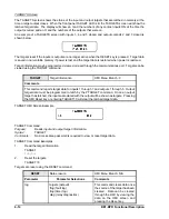
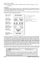
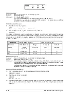
The RELAY SETUP menu screen shows the unique name of the protection logic scheme selected. Other
schemes may be selected pressing the EDIT +/- key with the cursor under the logic name. The relay will
scroll through the logic names stored in memory. The fault detector pickup and timer delay settings are dis-
played on the RELAY SETUP sub-screens. To change the relay pickup or timer settings, use the same
techniques described in this section, under
Changing Parameters.
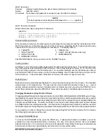
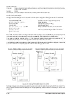
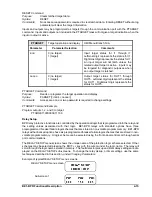
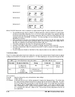
Example of typical RELAY SETUP menu screens:
RELAY SETUP menu screen
Sub-screen 1
Содержание BE1-BPR
Страница 1: ...Publication 9 2720 00 990 Revision E 12 98 INSTRUCTION MANUAL for BE1 BPR BREAKER PROTECTION RELAY...
Страница 31: ...BE1 BPR Application 2 17...
Страница 41: ...BE1 BPR Human Machine Interface 3 3 Figure 3 3 BE1 BPR Relay Horizontal Mount Front And Rear Views...
Страница 42: ...3 4 BE1 BPR Human Machine Interface Figure 3 4 BE1 BPR Relay Vertical Mount Front View...
Страница 43: ...BE1 BPR Human Machine Interface 3 5 Figure 3 5 BE1 BPR Relay Vertical Mount Rear View...
Страница 49: ...4 6 BE1 BPR Functional Description Figure 4 2 Enhanced BE1 BPR Menu Display Screens...
Страница 50: ...BE1 BPR Functional Description 4 7 Figure 4 3 Standard BE1 BPR Menu Display Screens...
Страница 94: ...5 4 BE1 BPR BESTlogic Figure 5 1 BESTlogic Function Blocks...
Страница 120: ...7 2 BE1 BPR Installation Figure 7 1 Overall Dimensions Figure 7 2 Cutout Dimensions Panel Mount...
Страница 121: ...BE1 BPR Installation 7 3 Figure 7 3 Overall Dimensions Vertical Mount...
Страница 122: ...7 4 BE1 BPR Installation Figure 7 4 Overall Dimensions Side View Vertical Mount...
Страница 123: ...BE1 BPR Installation 7 5 Figure 7 5 Panel Drilling Diagram Vertical Mount...

