4-24
BE1-BPR Functional Description
IA=3.00KA; IB=3.00KA
IC=3.00KA; IN=0.00KA
I(1-7)=0100000
T(1-6)=000000
F(1-3)=001
O(A,1-15)=0000000000000000
RECLOSER RESET
BREAKER CLOSED
DIAG: 1 OF 1 TIMER ALARM
5(/$< 67$786
,
2$
,$ .
,% .
,& .
,1 .
,D
,E
,F
,Q
5(&/26(5
5(6(7
',$* 121(
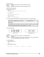
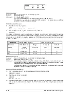
PHOLD Command Example
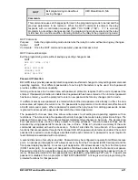
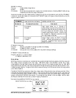
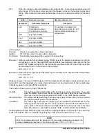
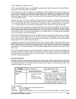
Disable the minimum hold time for output 3. Enable the minimum hold time for outputs 1, 2, 4, and 5.
PHOLD=11011
Relay Status
For diagnostic purposes, the RELAY STATUS menu screen provides a means of checking the status of the
current inputs, contact sensing inputs, output contacts, recloser, and relay diagnostics. This information can
also be obtained using the STATUS, I, and DIAG commands.
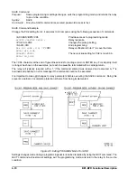
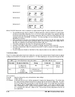
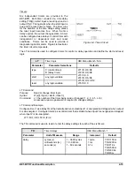
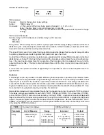
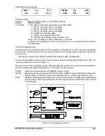
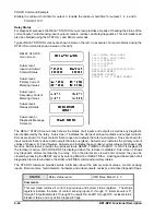
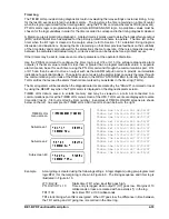
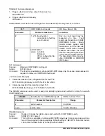
Typical RELAY STATUS screens are shown below on the left. An example of a report obtained using the
STATUS command is shown below on the right.
RELAY STATUS
menu screen
Sub-screen 1
Input and Output
Contact Status
Sub-screen 2
Primary Current
Metering Values
Sub-screen 3
Secondary Current
Metering Values
Sub-screen 4
Recloser Status
Sub-screen 5+
Diagnostic Message
Screen(s)
The RELAY STATUS menu branch shows the status of all inputs and outputs as well as any diagnostic
alarms detected by the relay. Sub-screen 1 indicates the status of all input contacts and output contacts.
Zeroes are shown for input contacts that are open and outputs that are de-energized. Ones are shown for
input contacts that are closed and outputs that are energized. Sub-screen 2 indicates the primary current
values of phase A, B, C and Neutral. Sub-screen 3 indicates the secondary current values of all phases and
Neutral. Sub-screen 4 provides the recloser status. RESET, TIMING, LOCKOUT, or WAIT is displayed if
the recloser is active. RECLOSER OFF is displayed when the recloser is disabled. Sub-screen 5 shows
any diagnostic alarms recorded by the relay. Once the alarms are viewed and corrected, they can be
cleared by pressing the RESET key or by entering DIAG=0 or RESET DIAG. A listing and description of all
diagnostic alarms is provided in the DIAG and PDIAG command summary tables.
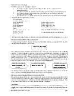
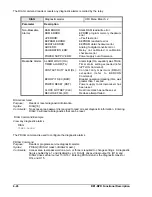
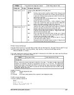
The STATUS command provides status information about the primary current values, contact sensing
inputs, timer/counters, fault detectors, hardware and virtual outputs, recloser, and active diagnostic flags.
STATUS
Relay status report
HMI Menu Branch: 2, 3
Comments
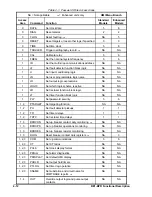
This command returns all current input values and system status registers. The status
registers indicate the state of contact sensing inputs I1 through I7, timers/counters T1
through T6, fault detectors F1 through F3, outputs OA, and O1 through O15, recloser status,
breaker status, and any active diagnostic flags.
Содержание BE1-BPR
Страница 1: ...Publication 9 2720 00 990 Revision E 12 98 INSTRUCTION MANUAL for BE1 BPR BREAKER PROTECTION RELAY...
Страница 31: ...BE1 BPR Application 2 17...
Страница 41: ...BE1 BPR Human Machine Interface 3 3 Figure 3 3 BE1 BPR Relay Horizontal Mount Front And Rear Views...
Страница 42: ...3 4 BE1 BPR Human Machine Interface Figure 3 4 BE1 BPR Relay Vertical Mount Front View...
Страница 43: ...BE1 BPR Human Machine Interface 3 5 Figure 3 5 BE1 BPR Relay Vertical Mount Rear View...
Страница 49: ...4 6 BE1 BPR Functional Description Figure 4 2 Enhanced BE1 BPR Menu Display Screens...
Страница 50: ...BE1 BPR Functional Description 4 7 Figure 4 3 Standard BE1 BPR Menu Display Screens...
Страница 94: ...5 4 BE1 BPR BESTlogic Figure 5 1 BESTlogic Function Blocks...
Страница 120: ...7 2 BE1 BPR Installation Figure 7 1 Overall Dimensions Figure 7 2 Cutout Dimensions Panel Mount...
Страница 121: ...BE1 BPR Installation 7 3 Figure 7 3 Overall Dimensions Vertical Mount...
Страница 122: ...7 4 BE1 BPR Installation Figure 7 4 Overall Dimensions Side View Vertical Mount...
Страница 123: ...BE1 BPR Installation 7 5 Figure 7 5 Panel Drilling Diagram Vertical Mount...

