BE1-BPR Functional Description
4-11
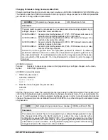
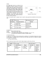
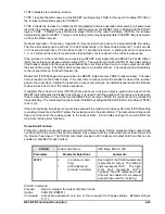
QUIT
Exit programming mode without
saving changes
HMI Menu Branch: N/A
Comments
This command causes all changes performed in the programming mode to be lost and the
previous parameters to be restored. When the QUIT command is entered, the relay
responds with a confirmation message (ARE YOU SURE (Y/N)?). If Y is entered,
programming or settings changes are lost, the programming mode is exited, and the relay
is returned to an on-line condition. Entering N returns the relay to the programming mode.
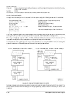
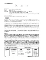
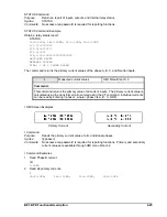
QUIT Command
Purpose:
Exits the programming mode and returns the relay to on-line without saving any changes.
Syntax:
QUIT
Comments:
Once the QUIT command is executed, password access is lost.
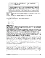
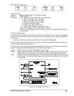
QUIT Command Example
Exit the programming mode without saving any setting changes made.
QUIT
ARE YOU SURE (Y/N)?
Y
RELAY OFF-LINE
CHANGES LOST
RELAY ON-LINE
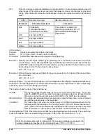
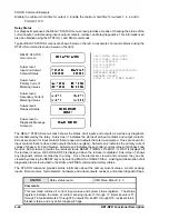
Password Protection
BE1-BPR relays provide password protection against unauthorized changes to relay setting parameters and
operating registers. Four different passwords of one to eight characters may be used. Each password
provides a different access capability.
Gaining write access in an access area with password protection requires that the correct password be
entered. If password protection is enabled and no password has been entered or if an incorrect password
has been entered, you will be prompted to enter a new password before any changes can be made.
If a different access area password is entered while another area password is already in effect, the new
access area will replace the current one. If a password is reprogrammed, it will not become effective until
a SAVE command is given. When a password is entered, the relay looks for matching passwords. Access
is granted to all areas with passwords that match the entered password.
The password for Access Area One allows write access to all setting and operating registers with no
restrictions. The Access Area Two password permits changes to be made to relay protection settings. The
password for Access Area Three allows breaker related settings changes to be made. The Access Area
Four password allows control of relay outputs for testing purposes. General access settings can be
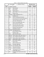
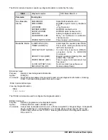
accessed by using passwords for areas one, two, or three. Table 4-1 provides a summary of the write
commands associated with each access area. Table 4-1 also lists the menu branch of the equivalent
functions that are accessible through the front panel HMI. When password protection is enabled, the correct
password is required to make changes associated with each command. A password is never required to
read information associated with a command.
A second dimension of security is provided. Passwords may be configured to operate from different access
ports. An access port designation of F allows access only from the Front panel (COM 0 serial port and the
front panel display/keyboard). An access port designation of R allows access only from the Rear panel
(COM 1 serial port). An access port designation of B allows access from Both the front and rear panels.
Password protection for a specific access area may be disabled by programming the password to be '0'
(zero). Password protection for ALL passwords may disabled by programming PW1 as a '0'. If a particular
password is disabled, then no prompts to "ENTER PASSWORD" will be given when programming the
protected functions for that password.
Содержание BE1-BPR
Страница 1: ...Publication 9 2720 00 990 Revision E 12 98 INSTRUCTION MANUAL for BE1 BPR BREAKER PROTECTION RELAY...
Страница 31: ...BE1 BPR Application 2 17...
Страница 41: ...BE1 BPR Human Machine Interface 3 3 Figure 3 3 BE1 BPR Relay Horizontal Mount Front And Rear Views...
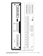
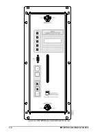
Страница 42: ...3 4 BE1 BPR Human Machine Interface Figure 3 4 BE1 BPR Relay Vertical Mount Front View...
Страница 43: ...BE1 BPR Human Machine Interface 3 5 Figure 3 5 BE1 BPR Relay Vertical Mount Rear View...
Страница 49: ...4 6 BE1 BPR Functional Description Figure 4 2 Enhanced BE1 BPR Menu Display Screens...
Страница 50: ...BE1 BPR Functional Description 4 7 Figure 4 3 Standard BE1 BPR Menu Display Screens...
Страница 94: ...5 4 BE1 BPR BESTlogic Figure 5 1 BESTlogic Function Blocks...
Страница 120: ...7 2 BE1 BPR Installation Figure 7 1 Overall Dimensions Figure 7 2 Cutout Dimensions Panel Mount...
Страница 121: ...BE1 BPR Installation 7 3 Figure 7 3 Overall Dimensions Vertical Mount...
Страница 122: ...7 4 BE1 BPR Installation Figure 7 4 Overall Dimensions Side View Vertical Mount...
Страница 123: ...BE1 BPR Installation 7 5 Figure 7 5 Panel Drilling Diagram Vertical Mount...


